background image

42


 A26361-K879-Z102-3-7619

Installing/Removing the Rack Model

Hardware Installation

Routing the Fibre Channel Optical Waveguide Cable

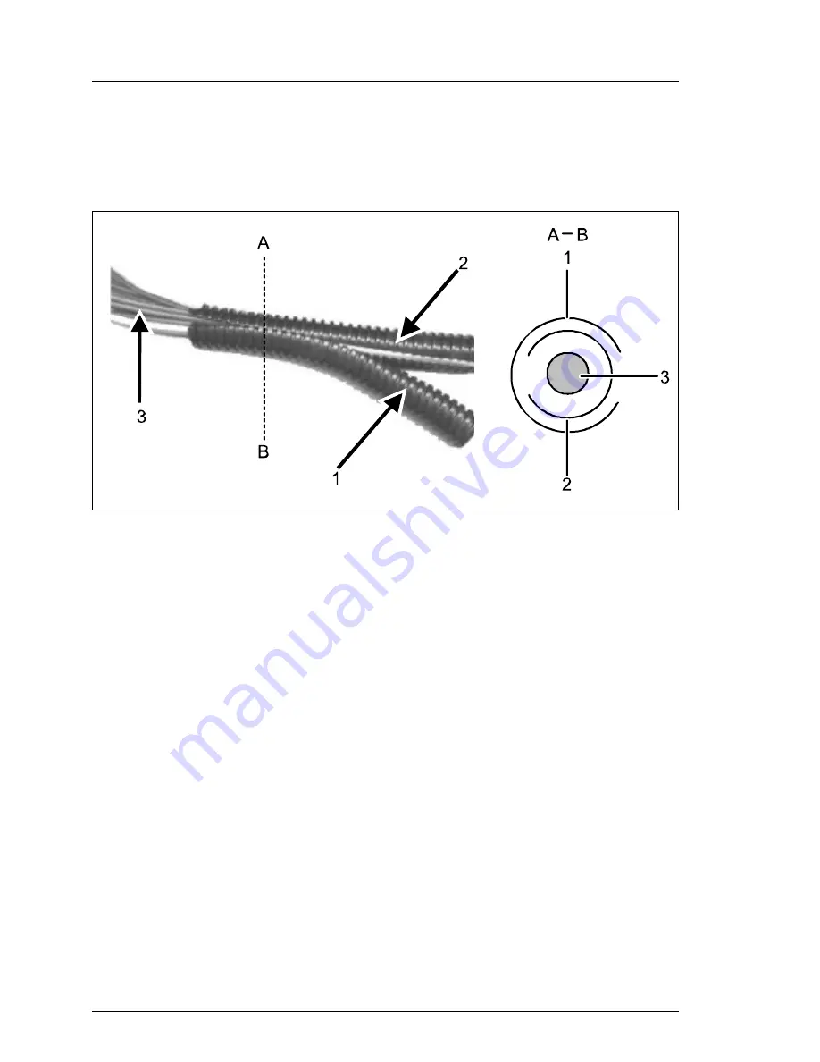
The protective hose (length approx. 1m) supplied with the mounting kit has a 
separable design.

Figure 16: Mounting the protective hose

Ê

Separate the outside protective sheath (1) from the inside sheath.

Ê

Carefully laid the fibre channel optical waveguide cable (3) into the inside 
protective sheath (2).

Ê

Push the outside protective sheath (1) over the inside protective sheath.

V

CAUTION!

The sheath openings must be arranged moving in opposite direction as 
shown in the sectional view A-B.

Содержание PRIMERGY TX150

Страница 1: ...ver System Operating Manual Ute Jacob Fujitsu Siemens Computers GmbH M nchen 81730 Munich e mail email manuals fujitsu siemens com Tel 089 61001 161 Fax 49 700 372 00000 A26361 K879 Z102 3 7619 Sprach...

Страница 2: ...epartment Certified documentation according DIN EN ISO 9001 2000 To ensure a consistently high quality standard and user friendliness this documentation was created to meet the regulations of a qualit...

Страница 3: ...tion Steps Overview Important Notes Hardware Installation Preparation for Use and Operation Property and Data Protection Problem Solutions and Tips Hot plug Hot swap Components Abreviations Related Pu...

Страница 4: ......

Страница 5: ...Bracket 27 4 4 Installing Removing the Rack Model 28 4 4 1 Mounting into the PRIMECENTER Rack 32 4 4 2 Mounting into the DataCenter Rack 35 4 4 3 Mounting into the Classic Rack 38 4 4 4 Mounting into...

Страница 6: ...Floppy Disk Cannot be Read or Written onto 70 7 8 Time and or Date are Incorrect 70 7 9 System Fails to Boot 70 7 10 Drives dead at System Boot 71 7 11 Added Drive Defective 71 7 12 Error Messages on...

Страница 7: ...ble rack door on the rack model The rack model occupies 5 height units in the rack 1 1 Overview of the Documentation I PRIMERGY manuals are available in PDF format on the ServerBooks CD The ServerBook...

Страница 8: ...available on the ServerBooks CD ServerStart Bundle includes the ServerStart CD the ServerBooks CD and the print version of the manual ServerStart Bundle The PDF file of the manual is also available on...

Страница 9: ...roller and a corresponding RAID config uration the HDD modules can be exchanged during operation hot swap A HDD extension box can be installed optionally with a maximum of three HDD modules Controllin...

Страница 10: ...redundant power supply two hot plug power supply units If one power supply unit fails the second power supply unit of the redundant configuration ensures unimpaired continued operation The defective p...

Страница 11: ...tion before a failure Watchdog timer for operating system monitoring and application monitoring with ASR R Further information on the ServerView server management is provided in the associated documen...

Страница 12: ...ies that must be performed in the order shown V CAUTION pay particular attention to text marked with this symbol Failure to observe this warning may endanger your life damage the server or lead to los...

Страница 13: ...0950 3rd Ed Electromagnetic Compatibility FCC class A VCCI class A AS NZS 3548 class A CNS 13438 Emitted interference EN 55022 class A Harmonic current EN 61000 3 2 JEIDA Flicker EN 61000 3 3 Noise im...

Страница 14: ...onment class 3K2 Environment class 2K2 DIN EN 60721 IEC 721 section 3 3 DIN EN 60721 IEC 721 section 3 2 Temperature Operation 3K2 Transport 2K2 10 C 35 C 25 C 60 C Relative humidity 10 85 Sound power...

Страница 15: ...le the server Please also refer to the section Connecting Devices to the Server on page 47 and section Instructions on Connecting Disconnecting Cables on page 51 Connect the system to the line voltage...

Страница 16: ......

Страница 17: ...onic office machines for use in an office environment If you have any questions contact your sales outlet or our customer service centre V CAUTION The actions described in these instructions should on...

Страница 18: ...y network with the IEC309 connector the public power supply protection must comply with the requirements for the non industrial public power supply networks for the type A connector The server automat...

Страница 19: ...ing a thunderstorm lightning hazard Make sure that no objects such as bracelets or paper clips fall into or liquids spill into the device risk of electric shock or short circuit In emergencies e g dam...

Страница 20: ...vice centre Batteries V CAUTION Incorrect replacement of batteries may lead to a risk of explosion The battery may only be replaced with an identical battery or with a type recommended by the manufact...

Страница 21: ...at high drive speeds data loss Under certain conditions sharp edged pieces of broken CDs can penetrate the cover of the drive damage to the device and be thrown out of the device danger of injury par...

Страница 22: ...fore working The equipment and tools you use must be free of static charge Remove the power plug from the power socket before inserting or removing components containing ESDs Always hold components wi...

Страница 23: ...e FCC rules and meets all requirements of the Canadian Interference Causing Equipment Standard ICES 003 for digital apparatus These limits are designed to provide reasonable protection against harmful...

Страница 24: ...es and equipment other than those specified by Fujitsu Siemens Computers The correction of interferences caused by such unauthorized modification substitution or attachment will be the responsibility...

Страница 25: ...sponding rack Ensure that the anti tilt bracket is correctly mounted when you set up the rack For safety reasons only one unit may be withdrawn from the rack at a time when performing assembly or serv...

Страница 26: ...on permanently should not be switched on until they need to be used and should be switched off during long breaks and on completion of work Notes on packaging Please do not throw away the packaging W...

Страница 27: ...nd disposal For details on take back and reuse of devices and consumables within Europe contact your Fujitsu Siemens Computers branch office subsidiary or our recycling centre in Paderborn Fujitsu Sie...

Страница 28: ......

Страница 29: ...Server Setting up the floorstand model see section Setting Up the Floorstand Model on page 25 or mounting the rack model into the rack see section Installing Removing the Rack Model on page 28 as sho...

Страница 30: ...mpleted It is recommended to not throw away the original packaging material It may be required for transportation at some later date Unpack all the individual parts Check the contents of the package f...

Страница 31: ...ce where you want to set it up Unpack the server see section Unpacking the Server on page 24 and the HDD cover The HDD cover is packed in a separate cardboard Figure 2 Mounting HDD cover Unlock the se...

Страница 32: ...her devices e g storage subsystem the rear of the server must be accessible The mains plug must be accessible easily and safely There must be a clearance of at least 200 mm in front of and behind the...

Страница 33: ...nti tilt Bracket For floorstand models with hot plug power supply units the supplied anti tilt bracket must be fitted at the rear of the server Figure 4 Mounting the anti tilt bracket Position the ser...

Страница 34: ...y precautions and references to rack instal lation in chapter Important Notes on page 11 At least two people are needed to position the server in the rack The rack may tip over if more than one unit i...

Страница 35: ...itsu Siemens Computers GmbH are PRIMECENTER Rack In connection with so called assembly brackets frontally bolted telescopic rails or sliding rails Two of these assembly brackets and or the sliding rai...

Страница 36: ...support of the cable management delivered with the mounting kit Climatic conditions For the ventilation of the installed server a large extent unhindered air intake in the rack front and air discharg...

Страница 37: ...7619 31 Hardware Installation Installing Removing the Rack Model Power supply For the installation in 3rd Party Racks it is to be made certain that appro priate socket strips are present Figure 6 Mec...

Страница 38: ...e brackets eight plugwashers figure 8 on page 33 I General information are provided in the Technical Manual for the PRIME CENTER Rack see also Related Publications on page 87 Figure 7 Prepare the tele...

Страница 39: ...ket at the appropriate height on the left rear support upright as described in the technical manual of the PRIMECENTER Rack To fasten the telescopic rails no flange nuts are necessary since the assemb...

Страница 40: ...e with the fact that two plugwashers each are used in the appropriate openings of the support uprights and or the support bracket see figure 8 on page 33 Adjust if necessary the length of the telescop...

Страница 41: ...igure 8 on page 33 I General information are provided in the Technical Manual for the DataCenter Rack see also Related Publications on page 87 Figure 10 Prepare the left telescopic rail Fasten the del...

Страница 42: ...fasten the telescopic rails in the groove of the support uprights at the marked attachment points Adjust the position of the nuts in the groove until they lock into the correct position The assembled...

Страница 43: ...les in the support upright Secure the end of the telescopic rail assembled with the bracket HL with two screws M4 2 on the support bracket in the rack Note with the fact that the two plugwashers are i...

Страница 44: ...ctive hose for fibre channel optical waveguide cable I General information are provided in the Technical Manual for the Classic 19 inch Rack see also Related Publications on page 87 Refer to the assem...

Страница 45: ...pring nuts must fit into the holes in the support uprights Mount the server see section Installing the Server on page 44 Mounting the Articulated Cable Carrier Cable Management V CAUTION In contrast t...

Страница 46: ...crews on the rear right support upright Figure 14 Routing the cables on the articulated cable carrier Route the cables as shown in the figure and secure them to the articulated cable carrier with cabl...

Страница 47: ...Securing the cables to the articulated cable carrier ensures that if the server is pulled out the articulated cable carrier extends themselves The server can be pulled out so later without further pr...

Страница 48: ...has a separable design Figure 16 Mounting the protective hose Separate the outside protective sheath 1 from the inside sheath Carefully laid the fibre channel optical waveguide cable 3 into the inside...

Страница 49: ...he folded condition of the carrier no damages can occur 4 4 4 Mounting into 3rd Party Racks For mounting the server in a 3rd Party Rack the following parts from the rack mounting kit are necessary two...

Страница 50: ...Mounting into the PRIMECENTER Rack on page 32 Mount the assembled telescopic rails with the brackets in the 3rd Party Rack as described in section Mounting into the PRIMECENTER Rack on page 32 Mount...

Страница 51: ...those of the server When doing this ensure that the telescopic bars are kept in a locked position Secure the telescope bars to the server using three M4x6 screws on the left side one screw on the cent...

Страница 52: ...ing the front panel in the corresponding holes of the front support uprights and fasten the server using four knurled screws 2 The HDD modules are provided with a transport lock Remove these before yo...

Страница 53: ...dditional ports are available on your server depends on the PCI boards installed The standard ports figure 22 are marked with symbols and some are color coded Figure 22 Floorstand model ports 1 Mouse...

Страница 54: ...gure 23 Rack model ports I Some of the devices that you connect require special driver software see the documentation for the connected device Connect the data cables to the server and peripherals You...

Страница 55: ...the mains socket strip of the rack V CAUTION The rated current for the monitor can be found on the technical data label on the monitor or in the operating manual for the monitor 4 6 Connecting the Se...

Страница 56: ...r 1 and the power plug to a grounded mains outlet 2 of the in house mains and or into the mains socket strip of the rack see Technical Manual of the rack I A phase redundancy in the power supply of th...

Страница 57: ...leads Turn off all power and equipment switches Unplug all power plugs of grounded power sockets Plug all cables into the server and peripherals Secure the data transmission cable connections e g nut...

Страница 58: ......

Страница 59: ...CAUTION Please note the safety instructions in chapter Important Notes on page 11 5 1 Locking and Unlocking the Floorstand Model Enabling access to the accessible drives Figure 25 Accessing the access...

Страница 60: ...the drive cover cannot be pushed into the top position and the hard disk drive cover cannot be removed Enabling access to the HDD modules Figure 26 Accessing the HDD modules Unlock the server 1 and re...

Страница 61: ...t 1 ON OFF button 8 Identification LED ID LED 2 Power on indicator 9 USB port 3 Hard disk drive active indicator 10 Hard disk drive control indicators figure 28 4 Global Error indicator 11 Floppy disk...

Страница 62: ...e To completely disconnect it from the mains voltage remove the power plug from the socket NMI NMI button I Please do not use it Using only from service reset Reset button Pressing the reset button re...

Страница 63: ...rvice incident or critical event has occurred Flashes orange when a critical event has occurred or a prefailure event has been recognized Users can check BIOS Setup system and eventlog or via ServerVi...

Страница 64: ...ction with a RAID controller does not light No HDD Error lights HDD Faulty or Rebuild Stopped drive defective needs replacing a rebuild process was stopped or the HDD module is not correctly inserted...

Страница 65: ...r orange Does not light when the system is ok No service incident or critical event has occurred Flashes orange when a critical event has occurred or a prefailure event has been recognized Users can c...

Страница 66: ...ng status is indicated by the LED 2 ID LED blue Pressing the ID button lights up the ID LEDs blue on the front and on the rear of the server The two ID LEDs are synchronized Lights up blue when the sy...

Страница 67: ...lation Press the ON OFF button position 1 in figure 27 on page 55 Insert the ServerStart CD and or an installation disk in the corresponding drive Follow the instructions on the monitor see also secti...

Страница 68: ...ntains information about configuring the server and installing the operating system I Make sure that the energy saving functions are disabled in the BIOS Setup during server operation 5 4 1 Configurat...

Страница 69: ...HostRAID The server is equipped with an onboard SCSI controller with HostRAID functionality I To configure HostRAID the controller has its own RAID Select Utility For further information see Adaptec H...

Страница 70: ...s job to a service technician Do not use any cleaning agents that contain abrasives or may corrode plastic Ensure that no liquid enters the system Ensure that the ventilation areas of the server and t...

Страница 71: ...you can achieve optimum protection for your system I You will find a detailed description of the System Security menu and how to assign passwords in the manual for the BIOS Setup and on the Server Bo...

Страница 72: ...e value Write Protect All Sectors or the value Write Protect Boot Sector for the Disk Drive Control field in the System Security menu Protecting BIOS from overwriting This function is currently not im...

Страница 73: ...ed as follows Make a note of the steps and the circumstances that led to the fault Note also any error message which may have been displayed Switch the server OFF Contact our Service organization 7 1...

Страница 74: ...r the appropriate password Brightness control is set too dark Adjust the brightness control to increase the brightness For detailed infor mation please refer to the operating manual supplied with your...

Страница 75: ...y 7 5 No Monitor Display or Display Drifts The wrong horizontal frequency and or resolution has been selected for the monitor or for the application programme Find out which horizontal frequency your...

Страница 76: ...he floppy disk drive controller and write permission are enabled see technical manual for system board at the PRIMERGY ServerBooks CD 7 8 Time and or Date are Incorrect Set the time and or date in the...

Страница 77: ...oller is not configured for this hard disk drive The drive was installed with the system switched OFF Reconfigure the RAID controller for the drive with the corresponding utility Information is contai...

Страница 78: ......

Страница 79: ...y be performed by maintenance staff 8 1 Hot plug Power Supply Units I As an option the fixed power supply unit can be replaced with one or two hot plug power supply units upgrading may only be perform...

Страница 80: ...r must be switched OFF Remove the cable from the installed power supply unit Push the locking bar of the installed power supply unit towards the power plug 1 Hold the bar firmly and pull the power sup...

Страница 81: ...supply unit contains a dummy unit This dummy unit must be removed before installing a second power supply unit Remove the dummy unit from the second power supply unit location I Installing removing t...

Страница 82: ...The hot swap procedure increases the availability of the system operation and guarantees a high degree of data integrity and protection against failure 8 2 1 Handling Hard Disk Drives HDD Modules Hard...

Страница 83: ...ay which is operating in RAID level 1 or 5 V CAUTION The HDD modules must be marked clearly so that they can be put back into its original place after an upgrade If this is not taken into account exis...

Страница 84: ...or future use If the HDD module is removed again and not replaced with a new module then the dummy module must be reinstalled due to cooling the applicable EMC electromagnetic compatibility regulation...

Страница 85: ...Drive Figure 33 Installing the HDD module Insert the HDD module with the opened handle carefully into the empty slot 1 until it stops Push the module handle completely in the original position 2 until...

Страница 86: ...ows If you want to pull out a HDD module which is not defective it must be set to offline via software RAID controller configuration software Pull out the HDD module defective not defective by a few c...

Страница 87: ...omatic Server Reconfiguration and Restart BIOS Basic Input Output System BMC Baseboard Management Controller CC Cache Coherency CD Compact Disk CD ROM Compact Disk Read Only Memory CHS Cylinder Head S...

Страница 88: ...nagement Interface ECC Error Checking and Correcting ECP Extended Capabilities Port EEPROM Electrically Erasable Programmable Read Only Memory EMC ElectroMagnetic Compatibility EMP Emergency Managemen...

Страница 89: ...Hard Disk Drive HSC Hot Swap Controller I C Inter Integrated Circuit I O Input Output ICM Intelligent Chassis Management ID Identification IDE Integrated Drive Electronics IRQ Interrupt Request Line L...

Страница 90: ...h NMI Non Maskable Interrupt NVRAM Non Volatile Random Access Memory OS Operating System PCI Peripheral Component Interconnect PDA Prefailure Detection and Analysing POST Power ON Self Test RAID Redun...

Страница 91: ...Bit Error SCA Single Connector Attachment SCSI Small Computer System Interface SDR Sensor Data Record SDRAM Synchronous Dynamic Random Access Memory SEL System Event Log SMI System Management Interru...

Страница 92: ......

Страница 93: ...e documentation available in the Internet can be found via the URL http manuals fujitsu siemens com choose intel based servers PRIMERGY ServerBooks 1 Safety and Ergonomics 2 Warranty 3 PRIMECENTER Rac...

Страница 94: ......

Страница 95: ...data manipulation 1 data protection 65 delivery note 24 devices connecting to the server 47 disconnecting cables 51 disposal of devices 21 drive dead 71 defective 71 indicators 57 dummy module HDD mod...

Страница 96: ...dule hot swapable 4 HDD Busy indicator 55 56 HDD extension box 3 HDD module acclimatization time 23 77 carrier 77 dummy module 76 handling 76 hard disk drive 77 hot swap 80 installing removing 77 heig...

Страница 97: ...configuring 63 PDA 4 5 plugwasher for telescopic rail 33 36 ports 47 keyboard port 47 LAN port 47 monitor port 47 mouse 47 parallel port 47 serial port 47 USB 47 55 power supply redundant 49 power su...

Страница 98: ...l 8 ON OFF button 55 56 operation 53 operator panel 55 parallel port 47 ports 47 power on indicator 56 property protection 65 reset button 55 56 routing cables 34 38 safety standards 6 7 serial port 4...

Страница 99: ...1 target group 1 technical data 6 telescopic rail 34 37 39 44 plugwasher 33 36 time wrong 70 transport damage 24 troubleshooting server 67 U unauthorized access 66 unpacking server 24 V ventilation cl...

Страница 100: ......

Страница 101: ...ystem A26361 K879 Z102 3 7619 Comments Suggestions Corrections Submitted by Fujitsu Siemens Computers GmbH User Documentation 81730 Munich Germany Fax 49 700 372 00000 email manuals fujitsu siemens co...

Страница 102: ......

Страница 103: ...ystem A26361 K879 Z102 3 7619 Comments Suggestions Corrections Submitted by Fujitsu Siemens Computers GmbH User Documentation 81730 Munich Germany Fax 49 700 372 00000 email manuals fujitsu siemens co...

Страница 104: ......

Страница 105: ...tsu com Copyright Fujitsu Technology Solutions 2009 Hinweise zum vorliegenden Dokument Zum 1 April 2009 ist Fujitsu Siemens Computers in den alleinigen Besitz von Fujitsu bergegangen Diese neue Tochte...

Отзывы: