


6-11
Possible Causes
What to Check and Suggested Measures
(2) The power to the inverter
was switched back on too
soon (with F14 = 1)
Check with LED monitor if the power to the inverter was
switched back on although its control circuit was still operating.
Î
Make the interval longer for re-power on.
(3) The power supply voltage
did not reach the range of
the inverter’s
specifications.
Measure the input voltage.
Î
Increase the voltage to within that of the specifications.
(4) Peripheral
equipment
for
the power circuit
malfunctioned, or the
connection was incorrect.
Measure the input voltage to find where the peripheral
equipment malfunctioned or which connection is incorrect.
Î
Replace any faulty peripheral equipment, or correct any
incorrect connections.
(5) Other loads were
connected to the same
power system and
required a large current to
start running to the extent
that it caused a temporary
voltage drop on the supply
side.
Measure the input voltage and check the voltage variation.
Î
Reconsider the power system configuration.
(6) Inverter's inrush current
caused the power voltage
drop because power
transformer capacity was
insufficient.
Check if the alarm occurs when you switch on a molded case
circuit breaker, a ground fault circuit interrupter (with
overcurrent protection) or a magnetic contactor.
Î
Reconsider the capacity of the power transformer.
[ 4 ]
NKP
Input phase loss protection
Problem
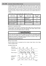
Input phase loss occurred, or interphase voltage unbalance rate was large.
Possible Causes
What to Check and Suggested Measures
(1) Main circuit power input
wires broken.
Measure the input voltage.
Î
Repair or replace the wires.
(2) The terminal screws for
the main circuit power
input of the inverter were
not tight enough.
Check if the screws on the inverter input terminals have
become loose.
Î
Tighten the terminal screws to the recommended torque.
(3) Interphase unbalance rate
of three-phase voltage
was too large.
Measure the input voltage.
Î
Connect an AC reactor (ACR) or a DC reactor (DCR) to
lower the rate.
Î
Raise the inverter capacity.
(4) Overload
cyclically
occurred.
Measure ripple wave of DC link bus voltage.
Î
If the ripple is large, raise the inverter capacity
(5) Single-phase voltage was
inputted to the inverter
instead of three-phase
voltage input.
Check the inverter type.
Î
Obtain a new inverter that meets the power supply
specifications.
Содержание Frenic Mini FRN001C1E-2U
Страница 60: ...3 15 Figure 3 5 shows the status transition for Menu 1 Data setting Figure 3 5 Data Setting Status Transition ...
Страница 85: ...5 4 ...
Страница 88: ...5 7 ...
Страница 89: ...5 8 C codes Control Functions of Frequency ...
Страница 92: ...5 11 J codes Application Functions y codes Link Functions ...
Страница 167: ...8 6 8 3 Common Specifications ...
Страница 168: ...8 7 ...
Страница 171: ...8 10 8 5 External Dimensions 8 5 1 Standard models ...
Страница 172: ...8 11 ...
Страница 173: ...8 12 8 5 2 Models available on order EMC filter built in type ...
Страница 174: ...8 13 ...
Страница 192: ...MEMO ...
Страница 193: ...MEMO ...
Страница 194: ...MEMO ...
Страница 196: ...Fuji Electric FA Components Systems Co Ltd Fuji Electric Corp of America 2007 06 F07 F07 00CM ...


