5-48
H07
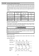
Acceleration/Deceleration Pattern
Specifies the acceleration and deceleration patterns (output frequency patterns).
Linear acceleration/deceleration
The inverter runs the motor with the constant acceleration and deceleration.
S-curve acceleration/deceleration
To reduce the impact on the inverter-driven motor during acceleration/deceleration,
the inverter gradually accelerates/decelerates the motor in both the accelera-
tion/deceleration zones.
Curvilinear acceleration/deceleration
The inverter drives the motor to output maximum performance with a constant
loading rate as follows:
- In the zone under the base frequency, linear acceleration/deceleration of con-
stant torque output for the motor
- In the zone above the base frequency, speed two times the base frequency and
acceleration/deceleration half of the base frequency
H12
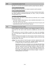
Instantaneous Overcurrent Limiting
Selects whether the inverter will perform current limiting processing or cause an
overcurrent trip if the output current exceeds the instantaneous overcurrent limit
level.
If the instantaneous overcurrent limiting is enabled, the inverter will immediately
turn off its output gates to suppress the increase of current and control the output
frequency.
If current limiting processing makes the motor decrease its torque temporarily so as
to cause any problem, then disable overcurrent limiting to cause an overcurrent trip
and apply brake to the motor.
The same functions to limit the output current are implemented by soft-
ware as function codes F43 and F44. Generally, software features have
an operation delay, so enable function code H12 as well.
Depending upon the load, acceleration in an extremely short period may
activate the current limiter to suppress the increase of the inverter output
frequency, causing the system oscillate (hunting) or making the inverter
enter the
W
Alarm mode and trip. When setting the acceleration time,
therefore, you need to take into account the load condition and moment of
inertia. Refer to the FRENIC-Mini User's Manual, Chapter 7, Section 7.1,
"Selecting Motors and Inverters."
Содержание Frenic Mini FRN001C1E-2U
Страница 60: ...3 15 Figure 3 5 shows the status transition for Menu 1 Data setting Figure 3 5 Data Setting Status Transition ...
Страница 85: ...5 4 ...
Страница 88: ...5 7 ...
Страница 89: ...5 8 C codes Control Functions of Frequency ...
Страница 92: ...5 11 J codes Application Functions y codes Link Functions ...
Страница 167: ...8 6 8 3 Common Specifications ...
Страница 168: ...8 7 ...
Страница 171: ...8 10 8 5 External Dimensions 8 5 1 Standard models ...
Страница 172: ...8 11 ...
Страница 173: ...8 12 8 5 2 Models available on order EMC filter built in type ...
Страница 174: ...8 13 ...
Страница 192: ...MEMO ...
Страница 193: ...MEMO ...
Страница 194: ...MEMO ...
Страница 196: ...Fuji Electric FA Components Systems Co Ltd Fuji Electric Corp of America 2007 06 F07 F07 00CM ...


