background image

127

=


8
8
8
8
5
5
5

Motor Plate Alu 4R s

Connector

Motor

[

Содержание VR 5000 noSpool

Страница 1: ...Perfect Charging Perfect Welding Solar Energy 42 0426 0080 EN 027 21122018 VR 5000 VR 5000 noSpool Operating Instructions Spare parts list Wire feed unit EN...

Страница 2: ...2...

Страница 3: ...reliable operation These are essential prerequisites for excellent results Explanation of safety notices DANGER Indicates immediate danger If not avoided death or serious injury will result WARNING In...

Страница 4: ...4...

Страница 5: ...ning maintenance and repair 17 Safety inspection 17 Disposal 18 Safety symbols 18 Data protection 18 Copyright 18 General information 19 General 21 Device concept 21 Requirements 21 Application area 2...

Страница 6: ...52 Feeding in the wire electrode 52 Setting the contact pressure 53 Adjust the brake 55 General 55 Adjusting the brake 55 Design of the brake 56 Start up 57 General information 57 Requirements 57 Weld...

Страница 7: ...6 Level 2 setup menu manual control panel 86 Level 2 setup menu Synergic control panel 86 Welding parameters for MIG MAG welding in the Setup menu level 2 88 Parameters for manual metal arc MMA weldin...

Страница 8: ...ransSteel 5000 US welding program tables 118 TransSteel 3500 Yard welding program tables 119 TransSteel 5000 Yard welding program tables 120 Quick reference 121 Appendix 123 Spare parts list VR 5000 1...

Страница 9: ...General in the operating instructions for the device Before switching on the device rectify any faults that could compromise safety This is for your personal safety Proper use The device is to be use...

Страница 10: ...g instructions especially the Safety rules section and sign to confirm that they have understood them and will follow them Before leaving the workplace ensure that people or property cannot come to an...

Страница 11: ...ive equipment Alternatively erect suitable safety screens curtains Danger from toxic gases and va pours The fumes produced during welding contain harmful gases and vapours Welding fumes contain substa...

Страница 12: ...re area between the body and the earth or ground potential All cables and leads must be secured undamaged insulated and adequately dimen sioned Replace loose connections and scorched damaged or inadeq...

Страница 13: ...fficiently insulated In the case of automated MIG MAG applications ensure that only an insulated wire elec trode is routed from the welding wire drum large wirefeeder spool or wirespool to the wire fe...

Страница 14: ...nd any part of the body Specific hazards Keep hands hair clothing and tools away from moving parts For example Fans Cogs Rollers Shafts Wirespools and welding wires Do not reach into the rotating cogs...

Страница 15: ...e corrosion or chang es caused by other environmental factors The testing interval and scope of testing must comply with applicable national standards and directives as a minimum Odourless and colourl...

Страница 16: ...ed gas leakage be fore every start up Safety measures at the installation location and dur ing transport A device toppling over could easily kill someone Place the device on a solid level surface such...

Страница 17: ...ant In addition all warranty claims will be forfeited Cooling Liquid FCL 10 20 does not ignite The ethanol based coolant can ignite under cer tain conditions Transport the coolant only in its original...

Страница 18: ...rea Ignoring this European Directive may have potentially adverse af fects on the environment and your health Safety symbols Devices with the CE mark satisfy the essential requirements of the low volt...

Страница 19: ...General information...

Страница 20: ......

Страница 21: ...he device has a Power limitation safety feature This means that the power source can be operated at the power limit without compromising process safety For more information see the Welding mode sectio...

Страница 22: ...s tance Do not use the functions described here until you have thoroughly read and un derstood the following documents these operating instructions all the operating instructions for the system compon...

Страница 23: ...g operation Keep hands and metal objects away 1 Electric shock can kill 1 1 Wear dry insulating gloves Do not touch electrode with bare hand Do not wear wet or damaged gloves 1 2 Protect yourself from...

Страница 24: ...weld on drums or any closed containers 4 Arc rays can burn eyes and injure skin 4 1 Wear hat and safety glasses Use ear protection and button shirt collar Use weld ing helmet with correct shade of fi...

Страница 25: ...Control elements and connections...

Страница 26: ......

Страница 27: ...tain functions that are not described in these operating instructions or vice versa Certain illustrations may also differ slightly from the actual controls on your device How ever these controls funct...

Страница 28: ...ameters in the Setup menu 2 Mode button for selecting the operating mode 2 step mode 4 step mode for selecting welding parameters in the Setup menu 3 Welding voltage adjuster for selecting the welding...

Страница 29: ...t aids have additional scales that correspond to the sheet thickness used If both the adjusters are set to the current value for the sheet thickness this will pro duce a good basic setting for the res...

Страница 30: ...gs can be retrieved Activate deactivate the keylock as follows Keylock activated The message CLO SEd appears on the displays Keylock deactivated The message OP En appears on the displays Service param...

Страница 31: ...gram Example iFd 0 0 Motor current for wire drive in A The value changes as soon as the motor is running 654 32 1 65 432 1 hours 65 432 hours 6 mins Indicates the actual arc time since using for the f...

Страница 32: ...al wire diameter and shielding gas to calculate the best weld ing parameters As a result stored knowledge is available at all times All the parameters can be adjusted manually The Synergic control pan...

Страница 33: ...selecting the following welding parameters Sheet thickness Sheet thickness in mm or in Welding current Welding current in A Before the start of welding the device automatically displays a standard val...

Страница 34: ...l panel are available as explained below Steel Yard Steel USA If one of these parameters is selected in the MIG MAG standard synergic welding process then the synergic function ensures that all other...

Страница 35: ...g the filler metal to be used Welding parameter SP is reserved for filler metals When a material is selected the LED behind the relevant filler metal lights up 1 2 3 1 2 3 Synergic B Steel control pan...

Страница 36: ...ve button can be retrieved provided that an assigned Save button was selected when the keylock was enabled Activate deactivate the keylock as follows Keylock activated The message CLO SEd appears on t...

Страница 37: ...welding program Example iFd 0 0 Motor current for wire drive in A The value changes as soon as the motor is running 654 32 1 65 432 1 hours 65 432 hours 6 mins Indicates the actual arc time since usin...

Страница 38: ...tional water connection is installed otherwise blanking co ver 3 Coolant return connection red option when the optional water connection is installed otherwise blanking co ver 4 Position for option cu...

Страница 39: ...blue option when the optional water connection is installed otherwise blanking cover Wire feed unit side No Function 1 Holder for braked wirespool for holding standard wirespools with a max diameter...

Страница 40: ...wire feed unit runs at wire threading speed Push button upwards to set the required quantity of gas at the pressure regulator Tap button once shielding gas flows out Tap button again shielding gas fl...

Страница 41: ...Installation and commissioning...

Страница 42: ......

Страница 43: ...n accordance with the intended purpose also comprises following all the information in the operating instructions carrying out all the specified inspection and servicing work Setup regulations WARNING...

Страница 44: ...44 The VR 5000 noSpool without an integrated wirespool holder may only be set up and op erated in closed areas...

Страница 45: ...a swivel pin holder is available e g VR 5000 swivel pin holder for use with the PickUp 5000 trolley Placing wire feed unit on power source CAUTION Danger from falling wire feed unit Make sure that th...

Страница 46: ...e steps described here until you have read and completely understood all the operating instructions NOTE When connecting the interconnecting hosepack check that all connections are connected properly...

Страница 47: ...the welding torch check that all connections are connected properly all cables leads and hosepacks are undamaged and correctly insulated Connecting MIG MAG manual welding torches 1 when the optional w...

Страница 48: ...ir possible areas of use can be found in the spare parts lists Inserting replac ing feed rollers CAUTION Risk of injury if the feed roller holders fly upwards When unlocking the clamping lever keep fi...

Страница 49: ...caused by the wire electrode springing back CAUTION Risk of injury from falling wirespool basket type spool Make sure that the wirespool or basket type spool with adapter is fitted securely to the wi...

Страница 50: ...terial damage if the basket type spool topples over because the locking ring has been placed the wrong way round Always place the locking ring as shown in the diagram on the left CAUTION Risk of injur...

Страница 51: ...51 EN 1 2 1 2...

Страница 52: ...torch trigger keep the welding torch away from your face and body and wear suitable protective goggles IMPORTANT To facilitate the exact positioning of the wire electrode the following se quences are...

Страница 53: ...not point the welding torch at people make sure that the wire electrode does not touch any conductive or earthed parts such as the housing etc IMPORTANT If the torch trigger is pressed instead of the...

Страница 54: ...54 1 Contact pressure standard values U groove roll ers Steel 4 5 CrNi 4 5 Tubular cored electrodes 2 3 1 1...

Страница 55: ...t the brake General NOTE After releasing the torch trigger the wirespool must stop unreeling If it continues unreeling readjust the brake Adjusting the brake 1 2 3 1 4 STOP 6 7 1 2 3 5 1 2 1 2 2 4 STO...

Страница 56: ...ectly can cause serious injury and damage Do not dismantle the brake Maintenance and servicing of brakes is to be carried out by trained qualified personnel only The brake is only available as a compl...

Страница 57: ...r for manual applications or by means of a welding start up signal for automatic applications Requirements When commissioning the wire feed unit the following requirements must be met Wire feed unit c...

Страница 58: ...58...

Страница 59: ...Welding...

Страница 60: ......

Страница 61: ...it is too high the arc gets smaller and smaller and may be extinguished In order to prevent this the welding power is lowered For the selected MIG MAG standard synergic welding process the symbol for...

Страница 62: ...me please refer to the Set up parameters section Symbols and their explanations Press the torch trigger Hold the torch trigger Release the torch trigger GPr Gas pre flow time I S Starting current can...

Страница 63: ...onger weld seams Special 4 step mode Special 4 step mode allows the starting and final current to be configured in addition to the advantages of 4 step mode Spot welding The Spot welding mode is suita...

Страница 64: ...n sheets to prevent the weld seams from dropping through the base material 4 step stitch welding The 4 step stitch welding mode is suitable for welding longer weld seams on thin sheets to prevent the...

Страница 65: ...the device make sure that the power source mains switch is in the O position the power source is unplugged from the mains General tasks be fore MIG MAG welding Only where cooling units and a water coo...

Страница 66: ...he Process button to select the desired welding process MIG MAG standard synergic welding Press the Mode button to select the desired MIG MAG mode 2 step mode 4 step mode Special 4 step mode IMPORTANT...

Страница 67: ...at people make sure that the wire electrode does not touch any conductive or earthed parts such as the housing etc press and hold the torch trigger turn the adjusting screw on the underside of the pr...

Страница 68: ...ing process MIG MAG welding Press the Mode button to select the desired MIG MAG mode 2 step mode 4 step mode IMPORTANT Under certain circumstances welding parameters that have been set on a control pa...

Страница 69: ...does not touch any conductive or earthed parts such as the housing etc Press the torch trigger and start welding Adjustments while welding manual control panel To obtain the best possible welding resu...

Страница 70: ...again If there is no Feeder inching Gas test button Press the Mode button to select 4 step mode Set the Ito parameter to Off in the set up menu Disengage the feed rollers CAUTION Risk of injury and da...

Страница 71: ...lts the arc force dynamic parameter will some times need to be adjusted Press the Parameter selection button to select the arc force dynamic parameter Use the adjusting dial to set the desired arc for...

Страница 72: ...welding Plug the grounding earthing cable into the or current socket depending upon which type of electrode is to be used and latch it by turning it clockwise With the other end of the earthing groun...

Страница 73: ...ically con ducting or earthed parts e g the housing etc Move the mains switch to the I position all the indicators on the control panel light up briefly Press the Process button to select the MMA weld...

Страница 74: ...Setup parame ters Setup menu level 2 Legend Hti Hot current time 0 2 s factory setting 0 5 s HCU HotStart current 100 200 factory setting 150 IH Main current set welding current Function During the s...

Страница 75: ...Press and hold the relevant Save button to delete the memory content of that Save button e g The left indicator displays Pro After a short time the left indicator switches to the original value Keep t...

Страница 76: ...76 Number 3 Number 4 Number 5...

Страница 77: ...Setup settings...

Страница 78: ......

Страница 79: ...ng welding parameters Exiting the setup menu Setup menu Synergic A con trol panel Setting the setup parameters is described here with reference to the MIG MAG standard synergic welding process The pro...

Страница 80: ...tup menu Press the Process button Release the Mode and Process buttons Use the Mode and Process buttons or the left hand adjusting dial to select the required setup parameter 3 4 5 Use the Parameter s...

Страница 81: ...l 4 step mode only Unit of welding current Setting range 0 200 Factory setting 100 I E I current End Final current special 4 step mode only Unit of welding current Setting range 0 200 Factory setting...

Страница 82: ...in 0 1 s increments Factory setting OFF FAC Factory Reset power source to factory setting Press and hold down the Dynamic manual control panel or Parameter selec tion Synergic A control panel button f...

Страница 83: ...t Unit of welding current Setting range 0 200 Factory setting 50 Fdi Feeder inching speed Unit m min ipm Setting range 1 max 39 37 max Factory setting 10 393 7 bbc burn back time correction Burn back...

Страница 84: ...ito 2nd Second level of the Setup menu see Setup menu level 2 Setup parameters for MMA welding IMPORTANT If you reset the power source using the FAC factory setup parameter the hot current time Hti a...

Страница 85: ...menu I S I current Starting Starting current Unit of welding current Setting range 0 200 Factory setting 100 SL Slope 0 9 9 s Unit s Setting range 0 9 9 Factory setting 0 I E I current End Final curr...

Страница 86: ...tton Press the Process button Release the Mode and Process buttons Use the Mode and Process buttons to select the 2nd setup parameter Press and hold the Mode button Press the Process button Release th...

Страница 87: ...dial to select the 2nd setup parameter 2 3 4 Press and hold the Mode button Press the Process button Release the Mode and Process buttons Use the Mode and Process buttons or the left hand adjusting d...

Страница 88: ...in the cooling sys tem the cooling unit will not cut out until the end of this pre set time Unit s Setting range 5 25 Factory setting 10 IMPORTANT Every time the power source is switched on the cooli...

Страница 89: ...o suit individual needs in Synergic operation If the ALC parameter is set to OFF the welding voltage cannot be adjusted The welding voltage is automatically determined by the selected welding current...

Страница 90: ...h or cross sectional area of the hosepack has changed measure the weld ing circuit resistance r again Measure the welding circuit resistance for every welding process separately with the appropriate w...

Страница 91: ...p parameter L is used to display the most recently calculated welding circuit in ductivity The welding circuit inductivity is calibrated at the same time as the welding circuit resistance r is calcula...

Страница 92: ...92...

Страница 93: ...Troubleshooting and maintenance...

Страница 94: ......

Страница 95: ...itable measuring device check to make sure that electrically charged com ponents e g capacitors have discharged CAUTION Inadequate PE conductor connections can cause serious injury and damage The hous...

Страница 96: ...overtemperature service codes to is displayed Detailed information on the service codes to0 to to6 can be found in the section Displayed ser vice codes Cause Overload Remedy Take the duty cycle into...

Страница 97: ...r liner in welding torch Remedy Check the inner liner for kinks dirt etc and replace if necessary Cause The feed rollers are not suitable for the wire electrode being used Remedy Use suitable feed rol...

Страница 98: ...emedy Use the correct shielding gas Displayed service codes If an error message that is not described here appears on the displays proceed as follows to resolve the problem Turn the power source mains...

Страница 99: ...e still remains switch off the power source wait for 10 seconds and then switch the power source on again if the error keeps recurring contact After Sales Service Err PE Cause The earth current watchd...

Страница 100: ...s risen above the tolerance range Remedy Check the mains voltage if the error keeps recurring contact the After Sales Service EFd 5 Cause Incorrect wire feed unit connected Remedy Connect correct wire...

Страница 101: ...Overtemperature in welding torch Remedy Allow welding torch to cool down to5 xxx Note xxx stands for a temperature value Cause Overtemperature in cooling unit Remedy Allow cooling unit to cool down c...

Страница 102: ...emperature in the cooling unit Remedy Place cooling unit in a heated room and allow to warm up tu6 xxx Note xxx stands for a temperature value Cause Undertemperature on the transformer of the power so...

Страница 103: ...ause The welding program selected is invalid Remedy Select valid welding program EPG 29 Cause The required wire feed unit is not available for the selected characteristic Remedy Connect correct wire f...

Страница 104: ...ARNING Work that is carried out incorrectly can cause serious injury and damage The following activities must only be carried out by trained and qualified personnel All instructions in the section hea...

Страница 105: ...Technical data and settings tables...

Страница 106: ......

Страница 107: ...re diameter 0 8 1 6 mm 0 03 0 06 in Wirespool diameter max 300 mm max 11 81 in Wirespool weight max 19 kg max 41 89 Ib Protection IP 23 Dimensions l x w x h 640 x 270 x 365 mm 25 20 x 10 63 x 14 37 in...

Страница 108: ...108 D C Duty cycle Wire diameter 0 8 1 6 mm 0 03 0 06 in Protection IP 20 Dimensions l x w x h 311 x 248 x 242 mm 12 25 x 9 76 x 9 54 in Weight 6 kg 13 23 Ib...

Страница 109: ...in 14 m min 551 18 ipm 23 4 V 1 5 mm 2 in 16 7 m min 657 48 ipm 27 V 0 6 mm 24 in 19 m min 748 03 ipm 27 8 V 0 8 mm 31 in 21 m min 826 77 ipm 30 4 V 0 10 mm 39 in 23 m min 905 51 ipm 32 6 V 0 12 mm 47...

Страница 110: ...ipm 34 V 0 15 mm 59 in 22 m min 866 14 ipm 35 V 0 20 mm 79 in 25 m min 984 25 ipm 36 9 V 0 Sheet thickness Wire feed speed Welding voltage Dynamic 1 mm 04 in 1 6 m min 62 99 ipm 15 5 V 3 1 5 mm 06 in...

Страница 111: ...4 m min 55 12 ipm 16 4 V 3 3 mm 12 in 2 2 m min 86 61 ipm 16 9 V 3 4 mm 16 in 2 8 m min 110 24 ipm 17 9 V 2 5 mm 2 in 5 3 m min 208 66 ipm 18 7 V 2 6 mm 24 in 4 m min 157 48 ipm 20 7 V 1 8 mm 31 in 4...

Страница 112: ...in 10 m min 393 7 ipm 24 V 3 6 mm 24 in 11 5 m min 452 76 ipm 24 9 V 2 8 mm 31 in 13 m min 511 81 ipm 25 5 V 2 12 mm 47 in 15 m min 590 55 ipm 29 5 V 1 15 mm 59 in 17 m min 669 29 ipm 32 V 0 20 mm 79...

Страница 113: ...oltage Dynamic 1 mm 04 in 1 4 m min 55 12 ipm 18 2 V 4 1 5 mm 06 in 1 7 m min 66 93 ipm 19 1 V 3 2 mm 08 in 2 2 m min 86 61 ipm 20 V 3 3 mm 12 in 3 1 m min 122 05 ipm 22 6 V 2 4 mm 16 in 4 2 m min 165...

Страница 114: ...114 20 mm 79 in 7 1 m min 279 53 ipm 33 V 1 25 mm 98 in 9 m min 354 33 ipm 40 V 1 Sheet thickness Wire feed speed Welding voltage Dynamic...

Страница 115: ...C D A B C D A C A C B C 1 Pos 1 1 1 2 2 2 3 3 3 3 4 4 5 5 6 6 7 Steel Steel Steel Steel Steel dynamic Steel dynamic Steel dynamic Steel root Steel root Steel root Steel root Rutil FCW Rutil FCW Basic...

Страница 116: ...B C D A C A C B C 1 Pos 1 1 1 2 2 2 3 3 3 3 4 4 5 5 6 6 7 Steel Steel Steel Steel Steel dynamic Steel dynamic Steel dynamic Steel root Steel root Steel root Steel root Rutil FCW Rutil FCW Basic FCW B...

Страница 117: ...c Steel dynamic Steel dynamic Steel dynamic Steel root Steel root Steel root Steel root Rutil FCW Rutil FCW Basic FCW Basic FCW Metal cored 100 CO2 0 8 mm 030 0 9 mm 035 1 0 mm 040 1 2 mm 045 1 4 mm 0...

Страница 118: ...dynamic Steel dynamic Steel dynamic Steel dynamic Steel root Steel root Steel root Steel root Rutil FCW Rutil FCW Basic FCW Basic FCW Metal cored 100 CO2 0 8 mm 030 0 9 mm 035 1 0 mm 040 1 2 mm 045 1...

Страница 119: ...utile E70T Basic E70T Basic Metal cored FCW Stainless Steel Self shielded 100 CO2 0 8 mm 030 0 9 mm 035 1 0 mm 040 1 2 mm 045 1 4 mm 052 1 6 mm 1 16 SP Ar O2 Ar 2 5 CO2 100 CO2 Ar 18 CO2 100 CO2 Ar 18...

Страница 120: ...ile E70T Basic E70T Basic Metal cored FCW Stainless Steel Self shielded 100 CO2 0 8 mm 030 0 9 mm 035 1 0 mm 040 1 2 mm 045 1 4 mm 052 1 6 mm 1 16 SP Ar O2 Ar 2 5 CO2 100 CO2 Ar 18 CO2 100 CO2 Ar 18 C...

Страница 121: ...2 T 2 step mode 4 T 4 step mode S 4 T Special 4 step mode Selecting the process Setting the mode MANUAL MIG MAG standard manual SYNERGIC Standard synergic STICK Manual metal arc welding Correcting par...

Страница 122: ...Final current 2 step special 4 step Starting current duration 2 step Final current duration 2 step Threading speed Burn back effect Length of wire before the safety cut out trips Restoring factory se...

Страница 123: ...Appendix...

Страница 124: ...4R G FSC Manual 4 049 009 VR 5000 Yard 4R G E Manual 4 049 009 001 VR 5000 Yard 4R G FSC Manual 4 049 009 800 VR 5000 Yard 4R G E Manual 4 049 009 801 VR 5000 Yard 4R G TW Manual 4 049 009 808 VR 500...

Страница 125: ...125...

Страница 126: ...126 E Euro connection Connectors F Fronius connection FSC Fronius system connection TW Tweco connection...

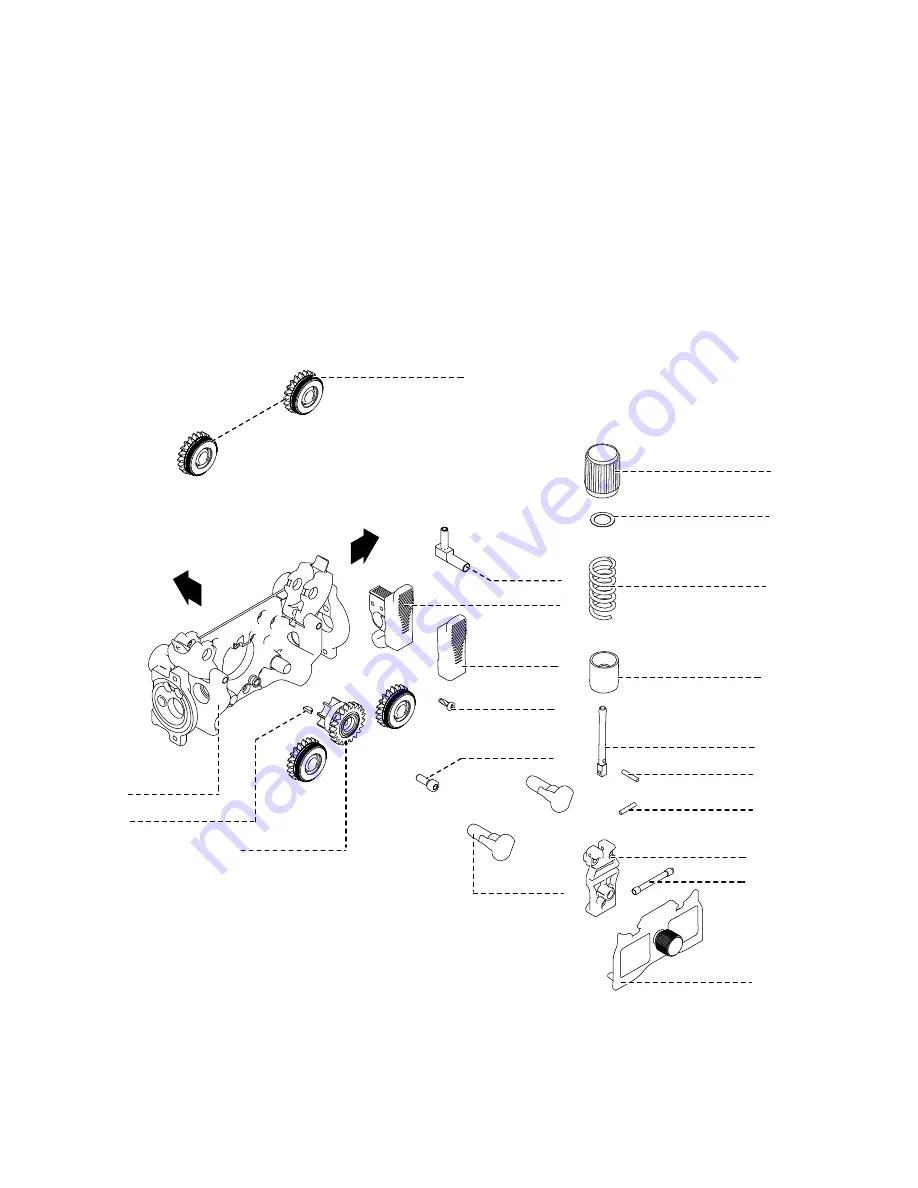
Страница 127: ...127 8 8 8 8 5 5 5 Motor Plate Alu 4R s Connector Motor...

Страница 128: ...128...

Страница 129: ...129...

Страница 130: ...130...

Страница 131: ...131...

Страница 132: ...1 A 4600 Wels Austria Tel 43 0 7242 241 0 Fax 43 0 7242 241 3940 E Mail sales fronius com www fronius com www fronius com addresses Under http www fronius com addresses you will find all addresses of...

Отзывы: