


QE128 Quick Reference User Guide, Rev. 1.0
Freescale Semiconductor
13-1
Chapter 13
Using the Output Compare function with the
Timer/Pulse-Width Modulator (TPM) module for the QE
Microcontrollers
13.1
Overview
This is a quick reference for enabling the PWM functionality of the timer/pulse-width modulator (TPM)
module on the QE family microcontrollers (MCUs). Basic information about the functional description
and configuration options is provided. The following example may be modified to suit your application.
The TPM project was made for the MC9S08QE128 and MCF51QE128 microcontrollers.
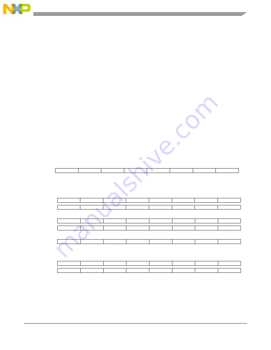
TPM Quick Reference
Because there is more than one TPM modules on QE MCU, there are three full sets of registers. In
the register names below, where there’s a small x, there would be a 1, 2 or 3 in your software to
distinguish the registers that are on TPM1 from those on TPM2 or from TPM3. A small n in a
register name below is a place-holder for the channel number.
Module configuration:
TPMxSC
TOF
TOIE
CPWMS
CLKSB
CLKSA
PS2
PS1
PS0
TOF – Timer Overflow Flag
CLKS[B:A] – Clock Source Select
TOIE – Timer Overflow Interrupt Enable
PS[2:0] – Prescale Divisor Select
CPWMS – Center-Aligned PWM Select
TPMxCNTH
Bit 15
14
13
12
11
10
9
Bit 8
TPMxCNTL
Bit 7
6
5
4
3
2
1
Bit 0
Any write to TPMxCNTH or TPMxCNTL clears the 16-bit counter
TPMxMODH
Bit 15
14
13
12
11
10
9
Bit 8
TPMxMODL
Bit 7
6
5
4
3
2
1
Bit 0
Modulo value for TPM module
TPMxCnSC
CHnF
CHnIE
MSnB
MSnA
ELSnB
ELSnA
CHnF – Channel n Flag
MSnA – Mode Select A for TPM Channel n
CHnIE – Channel n Interrupt Enable
ELSn[[B:A] – Edge/Level Select Bits
MSnB – Mode Select B for TPM Channel n
TPMxCnVH
Bit 15
14
13
12
11
10
9
Bit 8
TPMxCnVL
Bit 7
6
5
4
3
2
1
Bit 0
Captured TPM counter of input capture function OR output copare value for output compare of PWM function


