Fore Systems ES-2810 Скачать руководство пользователя страница 17

ES-2810 ATM Uplink Module User Guide

2 - 3

Installation

1. Turn off the switch.
2. Remove the plate covering expansion slot A.
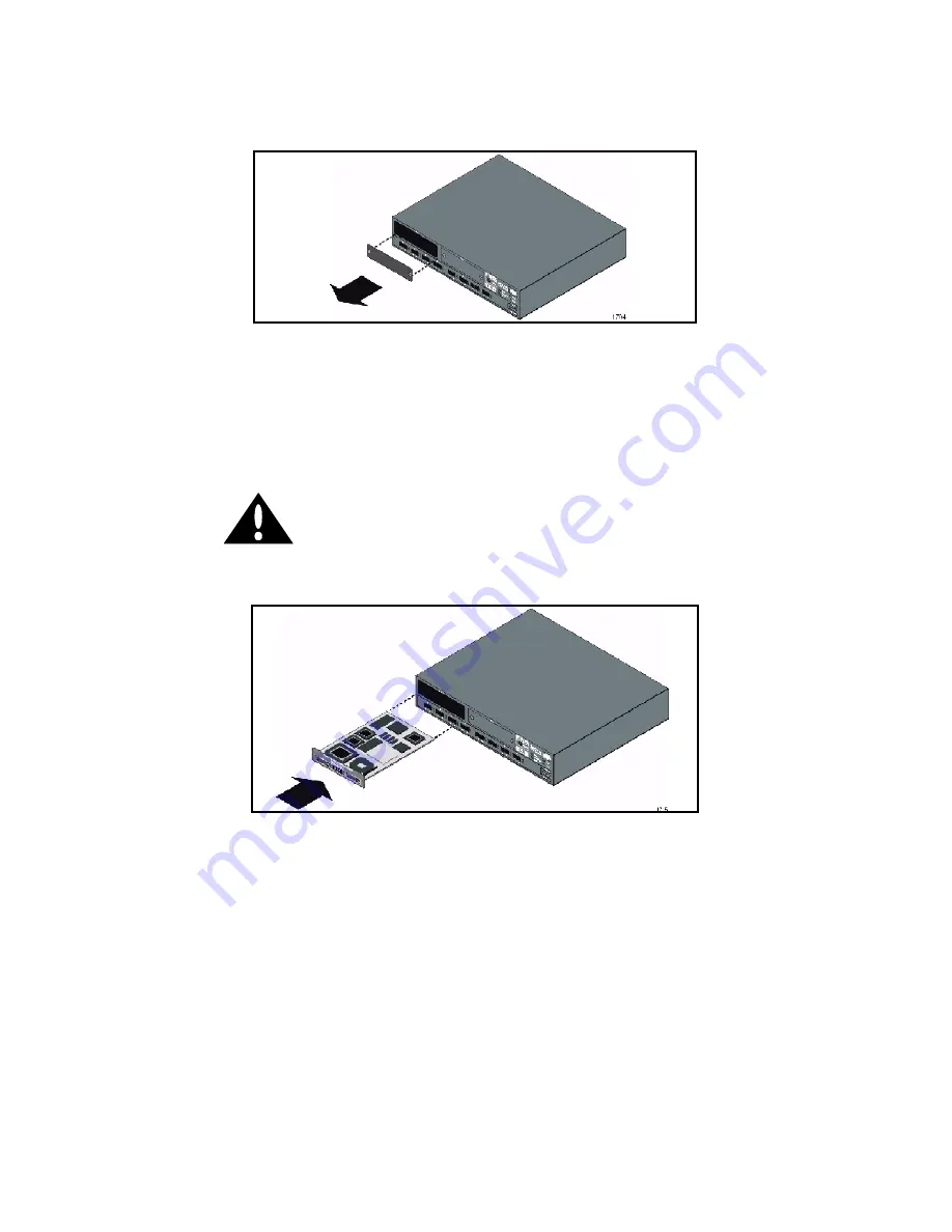
 

Figure 3 - 

Removing the Plate from Expansion Slot A

3. Insert the ATM Module into slot A. Place your thumbs just beneath the

screws on the front panel of the module and push firmly until the mod-
ule clicks into place. Secure the module using the retaining screws.

CAUTION

Do not over torque the retaining screws
when securing the module. Doing so may
damage the screws.

Figure 4 - 

Installing the ATM Module into Slot A

4. Connect the cables to the module. For details, see Section 2.5.
5. Turn on the switch.
6. Verify the links using the LEDs. For details about the LEDs, see Chap-

ter 1.

7. Configure the module using FORE Stack View. See Chapter 4.

Содержание ES-2810

Страница 1: ...ES 2810 Ethernet Switch ATM Uplink Module User Guide Firmware Version 5 2x MANU0400 02 Revision A June 1999 fs...

Страница 2: ...vernment other than DoD it is classified as Restricted Computer Software and the Government s rights in the Software are defined in paragraph 52 227 19 of the Federal Acquisition Regulations FAR or an...

Страница 3: ...this system meets or exceeds the following technical standards EN 55022 Limits and Methods of Measurement of Radio Interference Characteristics of Information Technology Equipment EN 50082 1 Electroma...

Страница 4: ......

Страница 5: ...1 4 CHAPTER 2 Installation 2 1 Unpacking and Checking Equipment 2 1 2 1 1 Checking the Package Contents 2 1 2 2 ESD Precautions 2 2 2 3 Installing the ATM Module 2 2 2 4 Removing an ATM Module 2 4 2 5...

Страница 6: ...ng the ATM Module 4 2 4 2 2 Changing the Port Mode Settings 4 3 4 2 3 Changing the LAN Emulation Configuration Server Setting 4 4 4 2 4 Changing the Module Mode 4 5 4 3 VLAN ELAN Mapping 4 6 4 3 1 Map...

Страница 7: ...overall description of the ATM Uplink Module Chapter 2 Installation Provides information on unpacking installing and ca bling the ATM Uplink Module Chapter 3 Upgrading Software and Firmware Provides i...

Страница 8: ...te ap plied to them Angle brackets are used to separate menu options specifying submenus For example Select File New Shortcut Important Information Indicators To call your attention to safety and othe...

Страница 9: ...hange the value of the LECS control parameters while the LECS process is running the new values do not take effect until the LECS process is stopped and then restarted Invisible Laser Warning Notice T...

Страница 10: ...re com 3 Telephone questions to support at 800 671 FORE 3673 or 724 742 6999 4 FAX questions to support at 724 742 7900 Technical support for customers outside the United States should be handled thro...

Страница 11: ...e Appendix A on page A 1 To differentiate the ATM Uplink Module from other modules used in the ES 2810 Stack Interface Modules Matrix Modules etc this manual refers to the ATM Uplink Modules as ATM Mo...

Страница 12: ...an ATM uplink failure on one module all ATM traffic is sent via the other operating module 1 2 Front Panel Features The front panel of an ATM Module features the following Status LEDs ATM Stack conne...

Страница 13: ...s of the LEDs Table 1 LED Description LED Label Color Meaning SIM Green SIM stack connection active switch has active connection to the Matrix Module Off SIM stack connection not active CPU Green CPU...

Страница 14: ...face Module Connector The 26 pin Stack Interface Module SIM connector adjacent to the ATM port en ables the module to be integrated into a stack This connector allows the Ethernet ports on the switch...

Страница 15: ...ing your ATM Module be sure to keep all original packing materi als They may be needed for storing transporting or returning the product NOTE All products returned to FORE Systems under warranty must...

Страница 16: ...the switch is grounded Equalize any static charge difference between your body and the switch by wearing a grounding wrist strap and attaching it to a non painted non isolated part of the grounded sw...

Страница 17: ...module and push firmly until the mod ule clicks into place Secure the module using the retaining screws CAUTION Do not over torque the retaining screws when securing the module Doing so may damage th...

Страница 18: ...e and secure using the screws 2 5 Cabling The cable connections to the ATM Module depend on the operating mode in which the module is to be used stand alone or stack 2 5 1 Stand Alone Mode Cabling Onc...

Страница 19: ...Module 2 Connect the ATM port on the ATM Module to an ATM switch on the ATM network The finished cabling should look similar to the following Figure 6 Stack Mode Cabling 2 switch stack 3 Check the LED...

Страница 20: ...installed in a stack In the event of an ATM uplink failure on one module all ATM traffic is sent via the other operating module The finished cabling should look similar to the following depending on...

Страница 21: ...check the following to ensure the module is working properly After the boot process has completed the CPU LED on the ATM Module should illuminate green for stand alone mode All LEDs should illuminate...

Страница 22: ...2 8 ES 2810 ATM Uplink Module User Guide Installation...

Страница 23: ...ades be completed via Ethernet attached TFTP or Bootp servers NOTE When loading ATM Module firmware for the first time or upgrading switch firmware to 2 5 for the first time you should use the initial...

Страница 24: ...all the older version The uninstall program will remove all components of the older FSV version from your computer and then in stall the newer version NOTE For detailed information about FORE Stack Vi...

Страница 25: ...FTP servers must be disabled before loading the firmware NOTE It is recommended to upgrade switch firmware and ATM Module firmware independently with switch firmware upgraded first Although the same u...

Страница 26: ...Firmware NOTE If there are two or more NICs in a PC you are prompted to select an IP address Select an IP address and click OK to proceed to the upgrade wizard 2 Click Next to continue with the upgra...

Страница 27: ...find a suitable version of the firmware to install the Firmware Not Found dialog box displays If the latest firmware is on a CD you must insert the CD and make sure that it can be accessed correctly I...

Страница 28: ...f where the upgrade file resides displays in the Path text field 4 Click OK The selected upgrade file displays in the Upgrade file text field 5 Click Next to continue with the upgrade wizard You are p...

Страница 29: ...recommended to upgrade switch firmware and ATM Module firmware independently upgrading switch firmware first 6 Make sure the Do not upgrade option has been selected and click Next The FORE Stack View...

Страница 30: ...es the presence of a TFTP server on the network During normal operation the Console port will give access to a menu identical to the one accessible via a telnet connection to the switch NOTE Upgrading...

Страница 31: ...tch Verify that switch is selected and press Enter to upgrade the switch 7 Launch your TFTP server If this is a first time upgrade specify the IP address of the TFTP server and the filename of the sof...

Страница 32: ...ode in maintenance mode Upgrading firmware via the console requires a TFTP server operating on an Ethernet segment attached to the switch NOTE For stack configurations you must upgrade the switch cont...

Страница 33: ...The uplink configuration remains intact when this upgrade procedure is used To use FSV to upgrade the ATM Module firmware you will need a Windows NT 95 98 client running FSV When FSV contacts the swit...

Страница 34: ...ion you are first prompted to select the switch you want to upgrade before the upgrade wizard window displays Highlight the switch and select Options Upgrade NOTE If there are two or more NICs in a PC...

Страница 35: ...Software and Firmware 2 Click Next to continue with the upgrade wizard You are prompted for the switch firmware upgrade file NOTE It is recommended to perform switch firmware and ATM Module firmware i...

Страница 36: ...ade file text field is blank indicating that switch firmware upgrade has not been selected 4 Select the Do not upgrade option to skip the switch firmware upgrade at this time The Do not upgrade option...

Страница 37: ...ith the ATM Module firmware upgrade If the upgrade wizard cannot find a suitable version of the firmware to install you are prompted for the location of the ATM Module firmware upgrade file 7 Click Br...

Страница 38: ...tware and Firmware 8 Locate the file and click Open The location of where the upgrade file resides displays in the Path text field 9 Click OK to continue with the upgrade wizard The selected upgrade f...

Страница 39: ...oftware and Firmware 10 Click Next The FORE Stack View software will launch a TFTP server utility perform the upgrade and reset the switch 11 After the upgrade has been completed and the switch has be...

Страница 40: ...have to create the management VLAN ELAN manually through FSV then restore the configuration 1 With a VT100 compatible terminal attached to the switch s Console port press Enter to display the Local Ma...

Страница 41: ...Settings Section 4 2 Configuring the Port Section 4 3 VLAN ELAN Mapping Section 4 4 Monitoring the ATM Module NOTE For detailed information on FORE Stack View and VLANs see the ES 2810 Ethernet Switch...

Страница 42: ...Labelling the ATM Module To help with identification and network management you can label the ATM Module With the switch or stack displayed in FSV complete the following steps to assign a unique name...

Страница 43: ...SONET Timing Internal and Cell insertion Unassigned To change the port mode settings complete the follow ing steps 1 With the ATM port selected from the FSV display select Configura tion Port Setup f...

Страница 44: ...eps 1 With the ATM port selected from the display select Configura tion Port Setup from the main menu or right click the ATM port and select from the pop up menu The Setup window displays 2 Select the...

Страница 45: ...e your configuration and reset the switch It is recommended to backup the configuration to disk before changing the mode NOTE A switch with an ATM Module in stand alone mode will not be recognized as...

Страница 46: ...nnot be changed since it is confined by the VLAN name To change the name delete the VLAN and re create it before mapping it to an ELAN You can use FORE Stack View FSV to do the following Create VLANs...

Страница 47: ...resses NOTE default and system ELAN VLAN names are not permitted These names are reserved by the network management systems where default ELAN maps to system VLAN NOTE When an ATM Module is installed...

Страница 48: ...r VLAN ELAN Spanning Tree Protocol STP can be enabled per VLAN ELAN STP provides loop free topology in a network environment that may have redundant paths To enable STP complete the following steps NO...

Страница 49: ...ES 2810 ATM Uplink Module User Guide 4 9 Configuring the Module 1 From the main menu select Configuration VLAN Setup The VLAN Setup window displays 2 Click Advanced The VLAN Advanced window displays...

Страница 50: ...LAN Span ning tree per VLAN is disabled by default 5 Click OK when finished 4 4 Monitoring the ATM Module FORE Stack View FSV 2 0 5 or greater allows you to monitor the performance of the ATM uplink p...

Страница 51: ...is described as follows Statistic Description AAL5 PDUs Transmitted Number of AAL5 protocol data units PDUs transmitted to the ATM switch Received Number of AAL5 PDUs received from the ATM network Dr...

Страница 52: ...if connected to an ASX switch port that is using SPANS signalling PMD Statistics Section BIP Number of Section Bit Interleaved Parity BIP errors Path BIP Number of Path BIP errors Line BIP Number of L...

Страница 53: ...ollowing steps 1 Right click on the ATM port and select from the pop up menu The ELAN Monitoring window displays 2 On the ELAN Table tab highlight the ELAN for which you want to access details and sel...

Страница 54: ...to view LE ARP cache information such as the MAC address to NSAP address mapping and VC type 4 Select File Exit to close the Details window 5 From the ELAN Port Monitoring main window select the ATM...

Страница 55: ...and one SONET SDH ATM uplink port ATM Uplink Data Rate 155 52 Mbps Maximum Line Length SIM and ATM Stack 39 inches 1 meter ATM uplink port 2 km 2000 meters Connector Type SIM and ATM Stack 26 position...

Страница 56: ...k Framing SONET Timing Internal Cell Insertion Unassigned Operating Temperature 0 to 55 C with 1 meter second air flow installed Storage Temperature 40 to 70 C installed Operating Humidity 10 to 90 no...

Страница 57: ...ing cable ATM uplink intermediate reach single mode fiber Table Size LE_ARP_CACHE at least 2000 addresses VCC Support up to 4096 VCCs Dimensions W 5 9 in 149 mm H 1 5 in 37 mm D 9 4 in 238 mm Weight 9...

Страница 58: ...link RJ 45 Media Type SIM and ATM Stack Stacking Cable ATM uplink Category 5 Unshield Twisted Pair Table Size LE_ARP_CACHE at least 2000 addresses VCC Support up to 4096 VCCs Dimensions W 5 9 in 149 m...

Страница 59: ...ns 155 Mbps UTP ATM uplink modules have a standard RJ 45 female connector and use RJ 45 network equipment pinouts as illustrated in the table below Pin Number Signal Mnemonic Signal Name 1 RX Receive...

Страница 60: ...A 6 ES 2810 ATM Uplink Module User Manual Technical Specifications...

Отзывы: