


M
ODEL
SDP100 V
ERSION
V_1.00
P
REPARED BY
H/W
D
ATE
25/05/2007
S
UBJECT
T
ECHNICAL
M
ANUAL
P
AGE
44/70
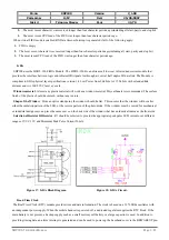
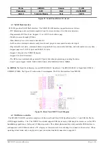
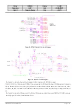
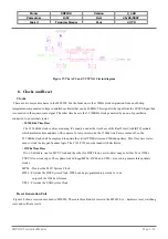
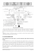
6.3 FM Radio Stage.
SDP100 Also, has a FM Radio chip set MT6188 from Media Tek. The interface is very simple. The FM_X1 frequency can be
used 32Khz, 13Mhz and 26Mhz. The FM_X1 is from MT6228 GPIO port can be used for Oscillator output. The L80 is to tune
the FM Radio band Q. Since the Headset is used for FM Radio Receiver and ANT. So, The Headset Receiver GND line must
be connected to GND via bead L40(22uH). If the Headset Receiver GND is connected to Power GND, The white noise is
increased.
Figure 34. FM Radio Circuit diagram.
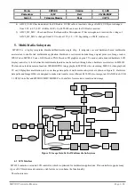
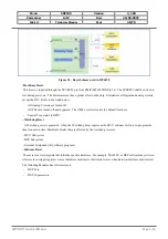
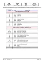
7.
Radio Interface Control
This chapter details the MT6228 interface control with the radio part of a GSM terminal. Providing a comprehensive control
scheme, the MT6228 radio interface consists of Baseband Serial Interface (BSI), Baseband Parallel Interface (BPI), Automatic
Power Control (APC) and Automatic Frequency Control (AFC), together with APC-DAC and AFC-DAC.
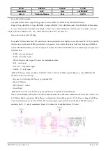
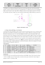
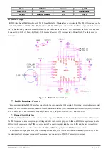
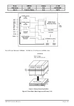
7.1 Baseband Serial Interface
The Baseband Serial Interface controls external radio components MT6120. A 3-wire serial bus transfers data to RF circuitry
for PLL frequency change, reception gain setting and other radio control purposes. In this unit, BSI data registers are double-
buffered in the same way as the TDMA event registers. The user writes data into the write buffer and the data is transferred
from the write buffer to the active buffer when a TDMA_EVTVAL signal(from the TDMA timer) is pulsed.
The unit has four output pins : BSI_CLK is the output clock, BSI_DATA is the serial data port and BSI_CS0,BSI_CS1 are
the select pins for 2 external components. These outputs are connected to MT6120 Transceiver to program.
SDP100
T
ECHNICAL
M
ANUAL
Page 3.44