


M
ODEL
SDP100 V
ERSION
V_1.00
P
REPARED BY
H/W
D
ATE
25/05/2007
S
UBJECT
T
ECHNICAL
M
ANUAL
P
AGE
39/70
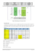
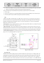
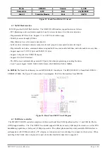
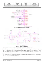
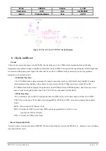
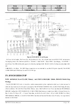
supports an arbitrary image size up to 640 pixels in height and 480 pixels in width. Figure 27 depicts the block diagram
of the TV controller and TV Encoder.
Figure 27. TV controller and Encoder block diagram.
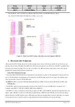
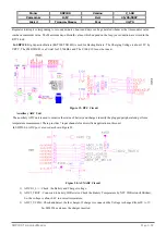
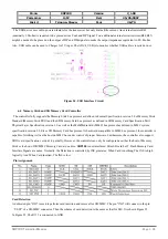
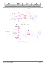
Figure 28. TV out Matching Circuit.
So, SDP100 has a TV out function. The Figure 28 is a TV out matching circuit. The TV video cable is a 75ohm impedance
and connected to I/O Connector CON40. The Audio Line is sharing with Melody Line.
6.
Audio Front-End
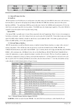
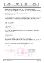
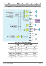
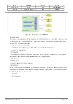
6.1 Main MIC, Receiver, Headset and OPamp stage.
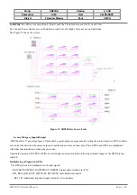
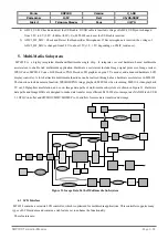
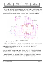
The audio front-end essentially consists of voice and audio data paths. Figure 29 shows the block diagram of the audio front-
end. All voice band data paths comply with the GSM 03.50 specification. Mono hands-free audio or external FM radio
playback paths are also provided. The audio stereo path facilitates CD-quality playback, external FM radio, and voice
playback through a headset. In SDP100, The Voice in normal mode is output to AU_Out0_N/P and voice in Headset
Mode/Loud Mode is output to AU_MOUTL/R . The Melody in Normal mode/Headset Mode is output to AU_MOUTL/R.
The Mic input in normal mode/Loud mode is to AU_VIN0_N/P and Mic input in headset mode is to AU_VIN1_N/P.
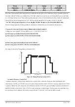
The below tables are shown the PGA gains of Mic, Voice and Melody. And the S/W control gain can be changed in Debug
Mode using *#110*01#
Æ
Audio
Æ
Normal mode/Headset Mode/Loud Mode.
SDP100
T
ECHNICAL
M
ANUAL
Page 3.39