


M
ODEL
SDP100 V
ERSION
V_1.00
P
REPARED BY
H/W
D
ATE
25/05/2007
S
UBJECT
T
ECHNICAL
M
ANUAL
P
AGE
31/70
2.
The most recent character was received longer than four character periods ago(including all start, parity and stop bit)
3.
The most recent CPU read of the FIFO was longer than four character periods ago.
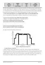
When virtual FIFO mode is enabled, RX Data timeout Interrupt is generated if all of the following apply:
1.
FIFO is empty.
2.
The most recent character was received longer than four character periods ago(including all start, parity and stop bit)
3.
The most recent CPU read of the FIFO was longer than four character periods ago
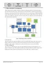
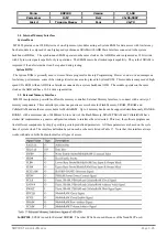
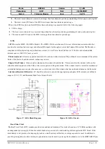
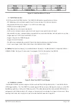
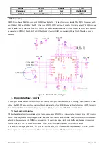
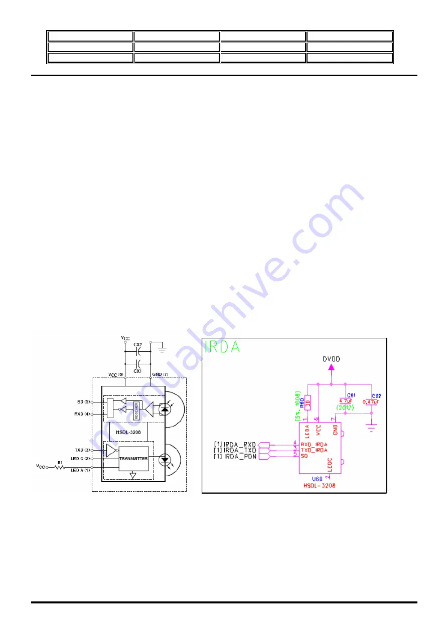
IrDA
SDP100 uses the HSDL-3208 IrDA Module. The HSDL-3208 is an ultra-small low cost infrared transceiver module that
provides the interface between logic and infrared(IR) signals for through air, serial, half duplex IR data link. The Module is
compliant to IrDA physical layer specifications version 1.4 Low Power from 9.6kbit/s to 115.2kbit/s with extended link
distance and it is IEC 825-Class 1 eye safe. .
Window material
: Almost any plastic material will work as a window material. Polycarbonate is recommended. The surface
finish of the plastic should be smooth, without any texture.
Shape of the Window
: From an optics standpoint, the window should be flat. This ensures that the window will not alter
either the radiation pattern of the LED, or the receive pattern of the photo diode. If the window must be curved for mechanical
or industrial design reasons, place the same curve on the back side of the window that has an identical radius as the front side
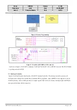
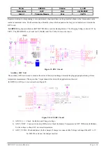
Selection of Resistor R1Resistor
: R1 should be selected to provide the appropriate peak pulse LED current over different
ranges of VCC 3.3V and Minimum Peak Pulse Current 50mA.
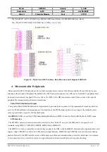
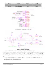
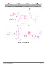
Figure 17. IrDA Block Diagram. Figure 18. IrDA Circuit.
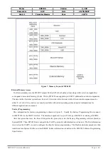
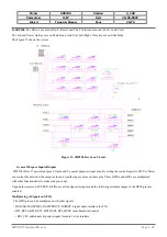
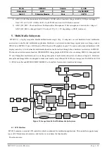
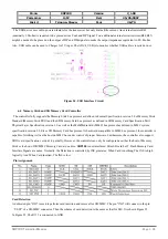
Read Time Clock
The Real Time Clock (RTC) module provides time and data information. The clock is based on a 32.768Khz oscillator with
an independent power supply. When the mobile handset is powered off, a dedicated regulator supplies the RTC block. If the
main battery is not present, a backup supply such as a small mercury cell battery or a large capacitor is used. In addition to
providing timing data, an alarm interrupt is generated and can be used to power up the baseband core via the BBWAKEUP pin.
SDP100
T
ECHNICAL
M
ANUAL
Page 3.31