


M
ODEL
SDP100 V
ERSION
V_1.00
P
REPARED BY
H/W
D
ATE
25/05/2007
S
UBJECT
T
ECHNICAL
M
ANUAL
P
AGE
36/70
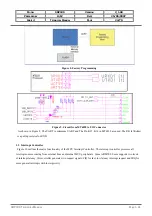
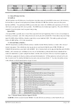
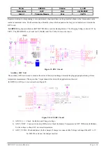
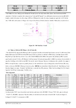
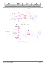
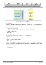
The USB device uses cable-powered feature for the transceiver but only drains little current. An external resistor R42
(nominally 1.5kohm) is required to be placed across Vusb and DP Signal. Two additional external serial resistors(R44,R45)
might be needed to be placed on the output of DP and DM signals to make the output impedance equivalent to 28~44ohm.
Also, USB cable can be used to Charger for 5V input. The ADC4_USB is to monitor whether USB cable is inserted or not.
Figure 24. USB Interface Circuit
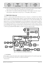
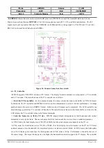
6.4
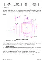
Memory Stick and SD Memory Card Controller
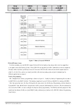
The controller fully supports the Memory Stick bus protocol as defined in Format Specification version 2.0 of Memory Stick
Standard (Memory Stick PRO) and the SD Memory Card bus protocol as defined in SD Memory Card Specification Part 1
Physical Layer Specification version 1.0 as well as the MultiMediaCard (MMC) bus protocol as defined in MMC system
specification version 2.2. Since SD Memory Card bus protocol is backward compatible to MMC bus protocol, the controller is
capable of working well as the host on MMC bus under control of proper firmware. Furthermore, the controller also support
SDIO card specification version 1.0 partially. However, the controller can only be configured as either the host of Memory
Stick or the host of SD/MMC Memory Card at one time.
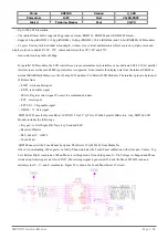
SDP100
is not interfaced Mini SD card but T-Flash Memory Card.
Interface Signals are same. Normally, the Detection is controlled by INS pin status. When Card is nothing, The INS is high
logically. And When Card inserted, The INS is low.
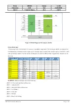
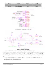
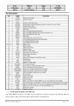
Pin Assignment.
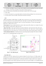
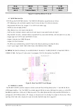
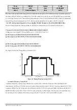
Card Detection
A dedicated pin “INS” is used to perform card insertion and removal for SD/MMC. The pin “INS” will connect to the pin
“
VSS2” of a SD/MMC connector. Then the scheme of card detection is the same as that for MS. It is shown Figure 25.
In Figure 25, The R115 is connected to GND.
SDP100
T
ECHNICAL
M
ANUAL
Page 3.36