


M
ODEL
SDP100 V
ERSION
V_1.00
P
REPARED BY
H/W
D
ATE
25/05/2007
S
UBJECT
T
ECHNICAL
M
ANUAL
P
AGE
41/70
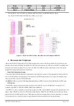
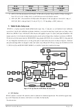
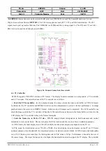
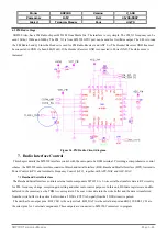
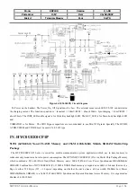
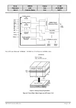
Figure 30. MT6228 Audio Port circuit diagram.
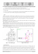
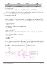
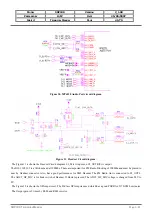
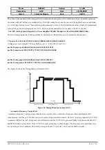
Figure 31. Headset Circuit diagram.
The Figure 31 is shown the Headset Circuit diagram. EJ_Mic is input and EJ_OUTR(L) is output.
The B101,102,103 is a 1Kohm bead at 100Mhz. These are important for FM Radio Blocking of 100Mhz and must be placed to
near by Headset connector. Also, has a good performance for EMI. Because The FM Radio Ant is connected to EJ_OUTL.
The ADC5_HF_MIC is for hook switch of Headset. If Hook is pressed, The ADC5_HF_MIC voltage is changed from 2.8V to
0V.
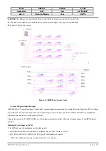
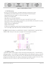
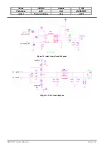
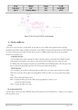
The Figure 32 is shown the OPAmp circuit. The D-Class OPAmp was used which has a good PSRR for 217 GSM burst noise.
The Output gain is 9 times by R600 and R603 resistor.
SDP100
T
ECHNICAL
M
ANUAL
Page 3.41