8
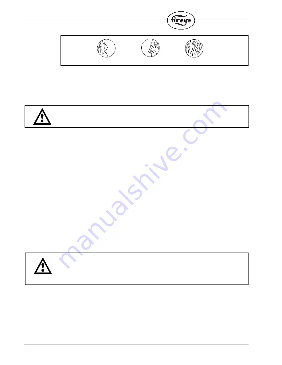
FLAME MUST COMPLETELY COVER SIGHT OPENING
6.
The preferred method for mounting surface mounted scanners requires the use of a swivel
mount, P/N 60-1664-3 (NPT), shown in Figure 5. Center the swivel mount over the two inch
hole in the burner plate and secure using three hexed cap screws (not provided). Install the sight
pipe on the swivel mount. If a swivel is not used, insert the end of the sight pipe into the hole,
align the hole to the desired viewing angle and tack weld (welding must be adequate to tempo-
rarily support the weight of the installed scanner). The sight pipe should be arranged to slant
downward so that dirt and dust will not collect inside.
CAUTION: Use no more than one foot of one inch diameter sight pipe. Increase the sight
pipe diameter one inch for every additional foot of sight pipe length used to avoid restricting
the scanner’s field of view.
7.
When a satisfactory sighting has been confirmed by operational testing, secure the swivel
mount’s ball position in place by tightening the three hex head cap screws located on the swivel
mount ring.
8.
For ease of use, the scanner should be installed on the sight pipe so the LED display can easily
be read.
Note: Operation of the LED display is independent of position.
9.
The scanner lens must be kept free of contaminants (oil, ash, soot, dirt) and the scanner housing
temperature must not exceed its maximum rating of 150° F (65° C). Excessive temperatures will
shorten scanner life. Both requirements will be satisfied by a continuous injection of purge air at
either the 3/8" housing inlet or the 1" “Y” connection ahead of the swivel mount as shown in
Figure 5.
The scanner mounting may be made with provision for purge air through only the 3/8" opening or for
purge air through either the 3/8" opening or the 1" “Y” connection. In the latter arrangements, normally
only one of the two connections is provided with purge air and the other connection is plugged. When a
sealing coupling is used, the 1" “Y” connection is used for the purge air and the 3/8" opening is plugged.
It is good practice to use the sealing coupling (P/N 60-1199-x with NPT threads) on all installations to
insure against unwanted furnace pressures from damaging the scanner lens.
Under normal conditions, with clean burning fuels and moderate ambient temperature conditions, purge
air flow of approximately 4 SCFM (113 l/min) is generally adequate. Up to 15 SCFM
(425 l/min) may be required for fuels that produce high levels of ash or soot, or for hot environments to
maintain the scanner’s internal temperature within specification.
BUT THIS
NOT THIS
NOT THIS
CAUTION: To ensure safe and reliable detection it is the responsibility of the commis-
sioning engineer to carry out flame failure testing after programming the scanner.
Ensure that the scanner correctly detects the target flame (Flame On condition) and rec-
ognizes the target flame off (Flame Off condition).


