


S2000 15017 Rev H 10/08/96 P/N 15017:H
55
A
NNUNCIATOR
I
NSTALLATION
Annunciator installation programming allows the programmer to tell the panel if a serial annunciator has been installed.
Note
After the system has been programmed, the Programming Key
must be removed to transfer the programming information
from temporary memory storage to nonvolatile memory.
Programming Annunciator Installation
The ANNUNCIATOR INSTALL LED will illuminate steadily. An illuminated green LED for notifica-
tion appliance circuit #2 represents an installed annunciator. Use the STATE CHANGE switch to
select or deselect annunciator installation. After programming annunciator installation, press the FUNC-
TION SELECT key to store the programming information and advance programming to the next func-
tion.
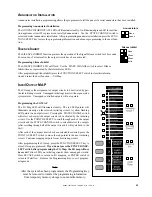
Annunciators
None
Annun
S
ILENCE
I
NHIBIT
The SILENCE INHIBIT function prevents the operation of the Signal Silence switch for 30 seconds,
60 seconds or 5 minutes after the output circuits have been activated.
Programming Silence Inhibit
The SILENCE INHIBIT LED will flash. Use the STATE CHANGE switch to select Silence
Inhibit time as represented by the Alarm Relay LEDs.
After programming Silence Inhibit press the FUNCTION SELECT switch to store this informa-
tion and select the next function I/O Map.
I
NPUT
/O
UTPUT
MAP
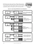
The I/O map is the assignment of output circuits to be activated by par-
ticular initiating circuits. Unmapped initiating circuits will not generate a
system alarm. Unmapped controlled outputs will not operate.
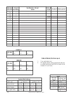
Silence Inhibit
None
30 sec
60 sec
5 min
Programming the I/O MAP
The I/O Map LED will illuminate steadily. The red LED pointer will
illuminate steadily on the selected initiating circuit. A yellow flashing
LED points to an output circuit. Pressing the STATE CHANGE switch
will select or deselect the output circuit to be activated by the initiating
circuit. Use the POINT B SELECT to scroll through each of the output
circuits and the STATE CHANGE switch to select/deselect the outputs
(after scrolling through all of the output circuits it will cycle back to the
first).
After each of the output circuits has been selected/deselected, press the
POINT A SELECT switch to move the red pointer to the next initiating
circuit. Continue mapping outputs for each initiating circuit.
After programming the I/O map, press the FUNCTION SELECT key to
store I/O map programmed.
If you do not press the FUNCTION SE-
LECT switch after programming the I/O Map, the I/O map will not
be saved.
Yellow LEDs on initiating circuits show unmapped circuits.
Press ESCAPE switch to return to I/O mapping, or ENTER switch to
return to Waterflow. Remove the Programming Key to exit program-
ming mode.


