


S2000 15017 Rev H 10/08/96 P/N 15017:H
16
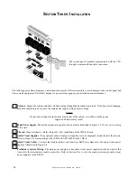
F
IGURE
3-3: I
NSTALL
THE
M
AIN
P
OWER
S
UPPLY
Place the MPS-24AF/MPS-24AFE (shown) or MPS-24BF/
MPS-24BFE into the bottom of the cabinet, ensuring that
the upper bracket engages the support bracket on the cabi-
net. Secure the bottom of the power supply to the bottom
cabinet support with the provided screws.
F
IGURE
3-4: I
NSTALL
THE
AVPS
Install any optional AVPS-24F/AVPS-24FE over the screw
mounts on the CHS-4 and secure with the two provided nuts.
F
IGURE
3-2: I
NSTALL
A
CHS-4
Install a CHS-4 in each row of the cabinet that will em-
ploy Sensiscan 2000 modules. For proper grounding of
the modules to the cabinet, connect a grounding cable to
one of the chassis mounting screws as illustrated.
F
IGURE
3-1 : M
OUNT
THE
CABINET
BACKBOX
Mount the backbox in a clean, dry, vibration free area, using the four
holes provided in the back surface of the cabinet.
Grounding Cable
CHS-4
AVPS
17-15/16