


S2000 15017 Rev H 10/08/96 P/N 15017:H
33
5.2
T
HE
MPS-24BF/MPS-24BFE M
AIN
P
OWER
S
UPPLY
Note:
The MPS-24BF has been designed to support single-cabinet row systems only.
This amounts to enough power for the CPU and up to three other modules as a maximum.
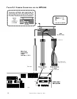
The MPS-24BF Main Power Supply is a supply capable of powering the system continuously during standby and alarm
conditions. A total of 750 mA @ 24 VDC regulated is available for operating the system during Standby conditions.
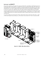
Figures 5-3 and 5-4 illustrate connections for primary and secondary power to the MPS-24BF Main Power Supply, as well
as terminal and harness connections.
C
ONNECTING
THE
P
RIMARY
P
OWER
S
OURCE
The MPS-24BF requires 120 VAC, 50/60 Hz, 1.8 amps primary power and the MPS-24BFE requires 220/240 VAC, 50/60
Hz, 0.9 amps. With the breaker at the main power distribution panel turned off, remove the plastic insulating cover from
Terminal Block TB1 and connect the system primary power source. Ground Cable per NEC requirements. Ground the
power supply assembly to the cabinet with a Chassis Ground cable (71073) to TB1 Terminal 2. Connect the primary Neutral
line to TB1 Terminal 3 and the primary Hot line to TB1 Terminal 4. Do not route 120 VAC wiring in the same conduit as
other control panel circuits. After completion of these connections reinstall the plastic insulating cover over the terminal
strip. Leave the main power breaker off until installation of the entire control panel is complete.
C
ONNECTING
THE
S
ECONDARY
P
OWER
S
OURCE
(24VDC)
Secondary power (batteries) is required to support the system during loss of primary power. These batteries reside in the
control panel cabinet. Connect the Battery Positive Cable to TB3 Terminal 1 (+) and the Battery Negative Cable to TB3
Terminal 2 (-).
Do not connect the Battery Interconnect Cable at this time. This connection will be made just after initial
primary system power-up.
E
ARTH
F
AULT
D
ETECTION
The MPS-24BF automatically employs detection of earth faults in the system (unless Resistor R55 is removed).
F
OUR
-W
IRE
S
MOKE
D
ETECTOR
P
OWER
(24VDC)
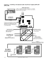
Up to 200mA of current for 24 VDC four-wire smoke detectors can be drawn from TB2 Terminals 1 (+) and 2 (-). Power is
removed from these terminals during system reset (unless Jumper JP1 is removed). This regulated four-wire smoke detector
power is power-limited but must be supervised via a UL-listed Power Supervision Relay. The power supervision relay is
energized by the four-wire power circuit and its contact must be connected in series with an initiating device circuit.
A
NNUNCIATOR
P
OWER
(24VDC)
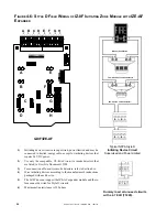
Up to 200mA of current suitable for powering an AFM-16ATF or AFM-32AF Annunciator can be drawn from TB2 Termi-
nals 1 (+) and 2(-). The power is regulated, power-limited and is supervised by the annunciator.
N
OTIFICATION
A
PPLIANCE
POWER
(24 VDC)
Up to 2.0 amps of regulated power-limited current for powering Notification appliances can be drawn from TB2 Terminals
3 (+) and 4 (-). Power is not removed from these terminals during system reset.
Do not connect any type of serial
annunciator (such as an AFM) or any device requiring filtered 24 VDC power to this circuit or damage may result!
S
YSTEM
H
ARNESS
C
ONNECTIONS
Internal power for the system is provided via the Power Harness (71086). Connect this harness from P2 on the MPS-24BF
to the CPU. Signaling between the CPU and the main power supply is accomplished through connection of the Power
Ribbon (71085) to P3 on the MPS-24BF.


