


S2000 15017 Rev H 10/08/96 P/N 15017:H
28
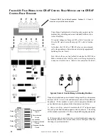
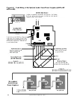
* Optional CRE-4F Control Relay Expander. Positions E, F, G and H
are active only with this board installed.
These Form-C gold-plated, silver alloy relay contacts are for
medium duty switching and are not intended for Motor Con-
trol or Pilot Duty.
UL contact ratings are 5 amps @ 125 volts AC (resistive) or
30 volts DC (resistive) and 2 amps @ 125 volts AC (induc-
tive).
Activation of a CR-4F or CRE-4F relay occurs automati-
cally when an alarm is detected on a selected (programmed)
Initiating Device Circuit.
no nc c no nc c no nc c no nc c
E
F
G
H
no nc c no nc c no nc c no nc c
A
B
C
D
A
E
B
F
C
G
D
H
★
★
★
★
Nonpower-limited and power-limited wiring must have a minimum
distance of 0.25" wire to wire and must enter and exit from different
knockouts. If this module is used to drive nonpower-limited and
power-limited circuits, please follow the instructions below.
1) Skip a set of dry contacts to maintain the 0.25" required space
between power-limited and nonpower-limited circuits. The wiring
of this module must follow UL Power-limited Wiring Requirements.
OR
2) If this module is needed to drive power-limited and nonpower-
limited relays that are next to each other, refer to the figure to the left
showing a typical connection.
NO
NO
NC
NC
NC
NO
C
C
C
NO
Relay 1
Relay 2
Relay 3
Relay 4
NC
C
Power-limited
Circuit
Power-limited
Circuit
Nonpower-limited
Circuit
Nonpower-limited
Circuit
no connection
Typical Form-C Control Relay in Standby Position
F
IGURE
4-8: F
IELD
W
IRING
OF
THE
CR-4F C
ONTROL
R
ELAY
M
ODULE
AND
THE
CRE-4F
C
ONTROL
R
ELAY
E
XPANDER
Note: Refer to the power-limited label located on the FACP door.
Make a notation on the label for each circuit being employed as
a nonpower-limited circuit. (Refer to the example on the label).


