


S2000 15017 Rev H 10/08/96 P/N 15017:H
14
S
ECTION
T
HREE
: I
NSTALLATION
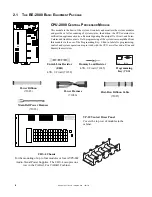
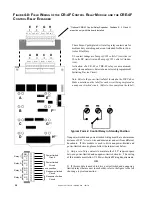
The control panel's modules communicate with the CPU
through a common ribbon cable connection.
The following procedures, diagrams, and instructions must be followed precisely to avoid damage to the control panel and
its associated equipment. Reliability depends to a great extent upon proper installation and maintenance.
❏
❏
❏
❏
❏
❏
❏
❏
❏
❏
❏
❏
❏
❏
❏
❏
❏
❏
❏
❏
❏
❏
❏
❏
❏
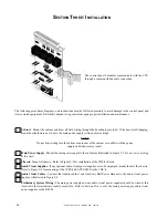
Cabinet
- Mount the cabinet and draw all field wiring through the knockouts provided. If the door is left-hanging,
mount door hardware now, due to the main power supply resting on lower hinge.
NOTE
Do not draw wiring into the bottom nine inches of the cabinet or conflict with the power
supply and batteries may result.
Main Power Supply
- Mount the main power supply to the cabinet as illustrated in Figure 3-3.
Do not wire anything
at this time!
Chassis-
Mount all chassis. Refer to Figure 3-2 for installation of the CHS-4 chassis.
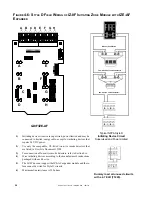
Audio Visual Supplies
- If any optional audio visual power supplies are to be employed, mount them to the chassis.
Refer to Figure 3-4 for mounting of the AVPS-24F/AVPS-24FE to the CHS-4.
Audio Visual Cables
- Connect the trouble cable(s) and Auxiliary Bell Power Harness to the audio visual power
supply as illustrated in Figure 5-4.
Preliminary System Wiring-
The main power supply and any audio visual power supplies should be wired at this
time while the terminals are readily accessible. Refer to Section Five to wire the main power supply, audio visual
power supplies or the R45-24.
❏
❏
❏
❏
❏


