


S2000 15017 Rev H 10/08/96 P/N 15017:H
27
b+ a+ a- b- b+ a+ a- b- b+ a+ a- b- b+ a+ a- b-
b+ a+ a- b- b+ a+ a- b- b+ a+ a- b- b+ a+ a- b-
E
F
G
H
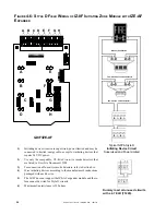
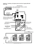
Optional ICE-4F Indicating Circuit Expander. Positions E, F, G, and H
are active only with this board installed.
4.7K, 1/2 watt ELR,
Part # 71252.
5
Jumper
unused
circuits
Jumper
unused
circuits
UL-listed
24 VDC
Polarized Horns
UL-listed
24 VDC
Polarized Bells
Typical
NFPA Style Y
Notification Appliance
Circuit
Typical
NFPA Style Z
Notification Appliance
Circuit
Cut this diode for California Code
F
IGURE
4-7: NFPA S
TYLE
Y/Z F
IELD
W
IRING
OF
THE
IC-4F I
NDICATING
C
IRCUIT
M
OD
-
ULE
AND
ICE-4F E
XPANDER
1)
Notification appliance circuits are supervised, power limited and may be connected to limited-energy cable.
2)
Use only compatible, UL-listed notification appliances that are listed in Document 15384.
3)
Wire notification appliances according to the manufacturer's instructions packaged with each device.
4)
Max current per circuit is 3.0 amps, subject to the limitations of the source of power (MPS-24AF/MPS-24AFE, MPS24BF/
MPS-24BFE, or AVPS-24F/AVPS-24FE).
5)
For Canada, model F-ELR End-of-Line Resistor Assembly is required.
6)
Size wiring for a maximum voltage drop of two volts at the last device on the circuit.
7)
The IC-4F is California Code programmable (microprocessor Rev. B or higher of IC-4F). To program for California Code, cut
diode D35.
8)
Cut jumper JP1 and JP2 to separately power notification appliance circuits 1 & 2 or 3 & 4. Separate 3 amps max. power
supplies must be tied to J5 & J6.
IC-4F/ICE-4F
A
B
C
D
A
E
B
F
C
G
D
H
D35
J5
J6
JP2


