


S2000 15017 Rev H 10/08/96 P/N 15017:H
37
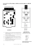
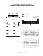
Figure 5-6 Connecting the R45-24 Remote Battery Charger
1
2
3
4
- +
- +
R45-24
+ -
Primary Power Source
Hot Neutral
PS-12550
12 VDC
55-AH
Battery
PS-12550
12 VDC
55-AH
Battery
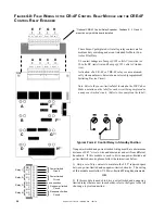
IMPORTANT!
1) Cut JP1 to disable on-board charger on the MPS-24AF.
2) Cut JP2 to disable on-board charger on the MPS-24BF.
TB2-6
PS-12550
Battery
PS-12550
Battery
TB2-2
TB2-1
TB2-5
MPS-24AF MPS-24BF
T
HE
R45-24/R45-24E R
EMOTE
B
ATTERY
C
HARGER
When the secondary requirements demand batteries that cannot be adequately charged by the main power supply employed,
an R45-24 Remote Battery Charger must be used. The R45-24 mounts in its own cabinet, up to 20 feet away (must be in the
same room as the control panel). The R45-24 is capable of charging 55 AH PS-12550 batteries, which are also contained in
the charger cabinet. For more information refer to the R45-24 Product Installation Drawing packaged with each unit.
C
ONNECTING
THE
P
RIMARY
P
OWER
S
OURCE
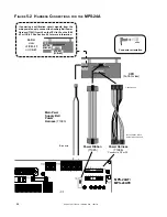
The R45-24 requires 120 VAC, 50/60 Hz primary power and the R45-24E requires 220/240 VAC, 50/60 Hz primary power.
With the breaker at the main power distribution panel turned off, connect the primary Hot line to Terminal 1 on the R45-24
and the primary Neutral line to Terminal 2. All connections between the Sensiscan 2000 and the R45-24 must be made in
conduit, using #12 AWG wire. Do not route VAC wiring in the same conduit as other Sensiscan 2000 circuits. Leave the
main power breaker off until installation of the entire system is complete.
C
ONNECTING
THE
S
ECONDARY
P
OWER
S
OURCE
(24VDC)
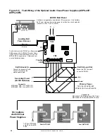
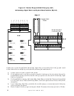
Do not connect AC power or batteries until the system is completely wired and ready for testing. Refer to Wiring Diagram
and instructions for the Fire-Lite R45-24 remote Battery Charger.
24 VDC. (supervised). Maximum charge current for standby batteries is 2 amps
(fast charge) or 20mA (trickle charge). Use #12 AWG wire in conduit (20 feet or
less, in same room).
+
-


