background image

32

DISPOSAL

SELECTION AND USE OF THE BRUSH

To dispose of the appliance, take it to a demolition centre or an 

authorised collection centre.

Before scrapping the appliance, it is necessary to remove and 

separate out the following materials, then send them to the 

appropriate collection centres in accordance with applicable 

environmental hygiene regulations:

•  Brushes

•  Felt

•  Electric and electronic parts*

•  Batteries

•  Plastic parts (tanks and handlebars)

•  Metal parts (levers and frame)

(*) In particular, contact your distributor when scrapping electric and 

electronic parts.

POLYPROPYLENE BRUSH (PPL)

Used  on  all  types  of  floors.  Good  resistance  to  wear  and  tear,  and  hot  water  (no  greater  than  50°C.). The  polypropylene  brush  is  non-

hygroscopic and therefore retains its characteristics even when working in wet conditions.

THICKNESS OF THE BRISTLES

Thicker bristles are more rigid and are therefore used on smooth floors or floors with small joints.

On uneven floors or those with deep joints, it is advisable to use softer bristles which can enter the gaps more easily.

Remember that when the bristles are worn and therefore too short, they will become rigid and are no longer able to penetrate and clean deep 

down. In this case, like with overlarge bristles, the brush tends to jump.

PAD HOLDER

The pad holder is recommended for cleaning shiny surfaces. 

There are two types of pad holder:

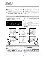
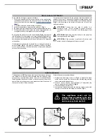
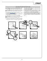
The traditional pad holder is fitted with a series of anchor points that allow the abrasive floor pad to be held and dragged while working.

the CENTRE LOCK type pad holder not only has anchor points, but also a snap-type central locking system in plastic that allows the abrasive 

floor pad to be perfectly centred and held without any risk of it becoming detached. This type of pad holder is recommended above all for 

machines with more than one brush, where the centring of the abrasive discs is difficult.

The undersigned manufacturer:

FIMAP S.p.A.

Via Invalidi del Lavoro, 1

37050 Santa Maria di Zevio (VR)

Declares under its sole responsibility that the products

FLOOR SCRUBBING MACHINE

 mod. Genie XS

comply with the requirements of the following Directives:

•  2006/42/EC: Machinery Directive.

•  2004/108/EC: Electromagnetic Compatibility Directive.

They also comply with the following standards:

•  EN 60335-1: Household and similar electrical appliances - Safety. 

Part 1: Generic standards.

•  EN 60335-2-72: Safety of household and similar electrical 

appliances. Part 2: Specific standards for automatic machines for 

floor treatment for commercial and industrial use.

•  EN 12100-1: Machine safety - Fundamental concepts, 

fundamental principles for design - Part 1: Basic terminology and 

methodology.

•  EN 12100-2: Machine safety - Fundamental concepts, 

fundamental principles for design - Part 2: Technical principles.

•  EN 61000-6-2: Electromagnetic compatibility (EMC) - Part 6-2: 

Generic standards – Immunity for industrial environments.

•  EN 61000-6-3: Electromagnetic compatibility (EMC) - Part 

6-3: Generic standards — Standard emission for residential, 

commercial and light-industrial environments.

•  EN 62233: Household and similar electrical appliances 

-  Electromagnetic  fields  -  Methods  for  evaluation  and 

measurement.

The person authorised to compile the technical file:

Mr. Giancarlo Ruffo

Via Invalidi del Lavoro, 1

37059 Santa Maria di Zevio (VR) - ITALY

Santa Maria di Zevio (VR), 07/01/2015

FIMAP S.p.A.

Legal representative

Giancarlo Ruffo

EC DECLARATION OF CONFORMITY

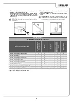
APPLIANCE

No. OF 

BRUSHES

CODE

TYPE OF 

BRISTLES

Ø


BRISTLES

Ø


BRUSHES.

NOTE

Genie XS

1

439929

PPL

1.1

280

PPL brush

1

439930

Pad holder

Содержание Genie XS

Страница 1: ...TRANSLATION OF THE ORIGINAL INSTRUCTION DOC 10049257 Ver AD 09 2015 PROFESSIONAL MICRO AUTOSCRUBBER USE AND MAINTENANCE MANUAL Genie XS...

Страница 2: ......

Страница 3: ...CE 10 MAIN APPLIANCE BODY COMPONENTS 10 MAIN SOLUTION TANK COMPONENTS 11 MAIN RECOVERY TANK COMPONENTS 11 MAIN VACUUM COVER COMPONENTS 11 MAIN STEERING COLUMN CONTROL COMPONENTS 11 MAIN HANDLEBAR CONT...

Страница 4: ...HECKING AND CLEANING THE VACUUM COVER 25 CHECKING AND CLEANING THE BRUSH 26 CHECKING AND CLEANING THE SQUEEGEE BODY 26 CHECKING AND CLEANING THE VACUUM HOSE 27 CHECKING AND CLEANING THE SOLUTION FILTE...

Страница 5: ...fest most appropriate and most autonomous way It includes information concerning technical aspects safety operation appliance downtime maintenance spare parts and scrapping Operators and qualified tec...

Страница 6: ...who is directly responsible for machine operation The majority of occupational accidents that happen both in the workplace or whilst moving are caused by failure to respect The serial number plate is...

Страница 7: ...mm 555 Machine length Handlebar in maintenance position mm 895 Machine body height Control handlebar joint mm 290 Control handlebar height Handlebar in resting position mm 1050 Machine height Handleb...

Страница 8: ...ct an authorised service centre immediately In the event of danger promptly remove the battery from the rear part of the appliance refer to the REMOVING THE BATTERY paragraph For all maintenance inter...

Страница 9: ...st have an earth connection in compliance with the regulatory standards The appliance does not cause harmful vibrations Never pick up gases explosive inflammable liquids or powders nor acids and solve...

Страница 10: ...Otherwise ask for intervention of the authorised technical assistance centre If you need to replace any components request the ORIGINAL spare parts from an Authorised dealer and or Retailer Restore a...

Страница 11: ...ance to indicate the direction in which the squeegee control handle must be turned in order to place in the working position SYMBOLS USED ON THE APPLIANCE PREPARING THE APPLIANCE HANDLING THE PACKED A...

Страница 12: ...es The handle 4 on the steering column control can also be used Fig 3 ATTENTION Users are advised to always wear protective gloves to avoid the risk of serious injury to hands ATTENTION When transport...

Страница 13: ...ONENTS MAIN STEERING COLUMN CONTROL COMPONENTS The pre assembly vacuum cover components are identified as follows 1 Vacuum cover stop lever 2 Floating support 3 Floats The steering column control base...

Страница 14: ...tion tank is empty otherwise empty it completely read paragraph ECHECKING AND CLEANING THE SOLUTION TANK 4 Block the handlebar in the vertical position Push the steering column control stop lever 2 in...

Страница 15: ...Other batteries could explode causing harm to people and damage to property The voltage rate indicated on the plate in the battery charger must correspond to the mains voltage Do not use the battery c...

Страница 16: ...tery proceed as follows 1 Take the appliance to the dedicated battery recharging area 2 If the appliance is working turn it off via the main switch 1 Fig 1 3 Block the handlebar in the vertical positi...

Страница 17: ...n inserting the battery into the base of the battery charger the red LED 11 present on the battery charger Fig 10 turns on This LED indicates that the battery is recharging 10 Perform a complete batte...

Страница 18: ...ch precedes the symbol The graphic symbol a line of luminous markings each bar corresponds to a of the charge If the charge level reaches a certain value the brush motor will switch off automatically...

Страница 19: ...ppliance taking care not to damage the vacuum hose inlet 6 on the vacuum motor and the squeegee body vacuum hose 7 When positioning the tank use the handles 3 on the solution tank to help Fig 7 and Fi...

Страница 20: ...Fig 1 and turn the steering column control into the horizontal position Fig 2 ATTENTION during this process keep the control handlebar still in order to prevent the appliance from moving accidentally...

Страница 21: ...ivered to the brush 9 During the first metres check there is sufficient solution and that the squeegee dries perfectly The appliance will now begin to work with full efficiency until the battery is fl...

Страница 22: ...ig 8 7 The appliance will now work efficiently dispensing the detergent solution and cleaning the floor until the battery runs down 8 During the first few meters check that the amount of detergent sol...

Страница 23: ...maximum level has been reached Fig 3 a further press on the button will return you to level 0 no detergent solution ATTENTION Passing from one step to another is a continuous cycle it is not possible...

Страница 24: ...top lever 3 to lock the handlebar Fig 5 7 Tilt the machine and move to a suitable place for carrying out maintenance work Fig 6 then complete the procedures listed in the paragraph RECOMMENDED PERIODI...

Страница 25: ...ease the stop lever 3 to lock the handlebar 11 Position the appliance with its rear part in contact with the floor Fig 9 ATTENTION Park the machine in an enclosed place on a flat surface near the mach...

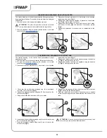
Страница 26: ...3 9 Rinse the inside with a jet of water if necessary use a spatula to remove the sludge that has accumulated at the bottom of the tank 6 Remove the vacuum cover using the stop levers Gently lay on t...

Страница 27: ...ctive gloves to avoid the risk of serious injury to hands 5 First with a jet of water and then with a damp cloth thoroughly clean the rotation fulcrum 2 on the vacuum motor floats Fig 3 6 First with a...

Страница 28: ...ssive wear replace the brush the bristles should be at least 10 mm long CHECKING AND CLEANING THE SQUEEGEE BODY The careful cleaning of the whole vacuum unit ensures better drying and cleaning of the...

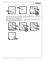
Страница 29: ...parts 6 Lift the squeegee attachment 1 Fig 4 7 Remove the squeegee from the slots on the squeegee connector 4 taking care not to lose the seal 5 on the vacuum nozzle Fig 5 8 First with a jet of water...

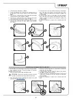
Страница 30: ...for filling the solution tank 2 Do what is required to make sure the machine is in a safe condition see MACHINE SAFETY 3 Disconnect the tank stop levers 1 and rotate in the direction indicated by the...

Страница 31: ...appliance taking care not to damage the vacuum hose inlet 6 on the vacuum motor and the squeegee body vacuum hose 7 When positioning the tank use the handles 9 on the solution tank to help Fig 11 and...

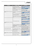
Страница 32: ...ry charger base The power supply cable plug is not correctly inserted in the mains socket Check that the battery charger power supply cable plug is connected to the mains socket The power supply netwo...

Страница 33: ...device is obstructed Make sure that the squeegee is free from obstructions read paragraph CHECK ING AND CLEANING THE SQUEEGEE BODY Make sure that the vacuum hose is free from obstructions read paragra...

Страница 34: ...ad to be perfectly centred and held without any risk of it becoming detached This type of pad holder is recommended above all for machines with more than one brush where the centring of the abrasive d...

Страница 35: ......

Страница 36: ...FIMAP S p A Via Invalidi del Lavoro 1 37059 S Maria di Zevio Verona Italy Tel 39 045 6060411 Fax 39 045 6060417 E mail fimap fimap com www fimap com...

Отзывы: