12
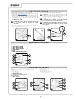
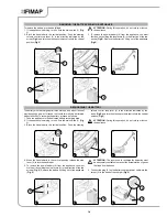
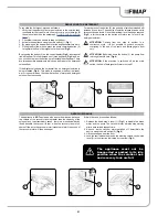
MAIN HANDLEBAR CONTROL COMPONENTS
The handlebar control components are identified as follows:
1. “AUTOMATIC” mode button.
2. “ECO - MODE” button.
3. “DETERGENT SOLUTION” regulation control button.
4. “VACUUM MOTOR” activation-de-activation button.
5. Display.
6. Dead man's lever.
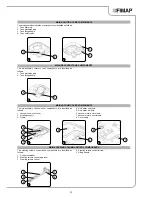
MAIN BATTERY CHARGING BASE COMPONENTS
APPLIANCE SAFETY
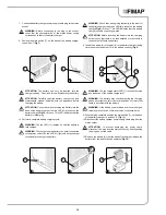
The basic components of the battery charger base are identified as
follows:
1. Battery.
2. Battery charger base.
3. Battery charger base power supply cord.
4. Battery charger main switch.
5. Battery stop lever.
The stages for making the appliance safe, and thereby allowing all
the operations to be carried out in complete safety, are as follows:
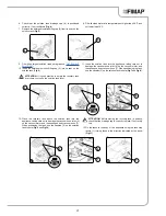
1. If the appliance is working, turn it off via the main switch (1) (
Fig.
1
).
2. Make sure the recovery tank is empty, otherwise empty it
completely (read paragraph “
CHECKING AND CLEANING THE
RECOVERY TANK
”).
3. Make sure the solution tank is empty, otherwise empty it
completely (read paragraph “
ECHECKING AND CLEANING THE
SOLUTION TANK
”).
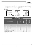
4. Block the handlebar in the vertical position. Push the steering
column control stop lever (2) in the direction indicated by the
arrow (
Fig.2
) and turn the steering column control into the vertical
position (
Fig.3
).
6. Green LED - power supply continuity to battery charger
7. Red LED - battery charge level.
8. Battery charger base socket.
9. Battery charger base power supply cable plug.
10. Battery charger base connection cable plug.
ATTENTION:
During this operation, do not rest your foot on
the appliance.
5. When the handlebar is in the vertical position, release the stop
lever (2) to lock the handlebar.
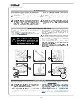
6. To remove the power battery (4) from the appliance, you must
first free it by shifting the stop levers (3) in the direction of the two
arrows (
Fig. 4
). Remove the battery by lifting out of the appliance
(
Fig. 5
).
ATTENTION:
The place this operation is carried out should
comply with current environmental protection regulations.
4
3
6
2
5
1
2
1
1
1
2
3
6
8
4
7
2
10
9
1
1
2
3
4
3
2
OFF


