3. Installation
3−32
Festo P.BE−VIFB11−03−EN en 0503g
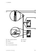
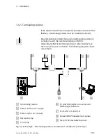
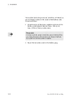
The required terminating resistance (120 Ohm, 0.25 Watt) can
also be cheaply installed in the socket of the fieldbus cable.
Proceed as follows:
1. Clamp the wires of the resistor together with those of the
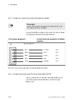
fieldbus cable between the wires Data + (PIN 4) and
Data− (PIN 5) of the bus cable socket.
Please note
In order to ensure proper connection, we recommend that
you clamp the wires of the resistor and those of the field
bus cable in a common cable end sleeve.
2. Mount the bus cable socket on the fieldbus plug.
Содержание IFB11-03
Страница 2: ......
Страница 4: ...Contents and general instructions II Festo P BE VIFB11 03 EN en 0503g...
Страница 18: ...Contents and general instructions XVI Festo P BE VIFB11 03 EN en 0503g...
Страница 19: ...Summary of components 1 1 Festo P BE VIFB11 03 EN en 0503g Chapter 1...
Страница 28: ...1 Summary of components 1 10 Festo P BE VIFB11 03 EN en 0503g...
Страница 29: ...Fitting 2 1 Festo P BE VIFB11 03 EN en 0503g Chapter 2...
Страница 39: ...Installation 3 1 Festo P BE VIFB11 03 EN en 0503g Chapter 3...
Страница 71: ...Commissioning 4 1 Festo P BE VIFB11 03 EN en 0503g Chapter 4...
Страница 89: ...4 Commissioning 4 19 Festo P BE VIFB11 03 EN en 0503g Fig 4 4 I O configuration DLC 100...
Страница 122: ...4 Commissioning 4 52 Festo P BE VIFB11 03 EN en 0503g...
Страница 123: ...Diagnosis and error treatment 5 1 Festo P BE VIFB11 03 EN en 0503g Chapter 5...
Страница 144: ...5 Diagnosis and error treatment 5 22 Festo P BE VIFB11 03 EN en 0503g...
Страница 145: ...Technical appendix A 1 Festo P BE VIFB11 03 EN en 0503g Appendix A...
Страница 159: ...Accessories B 1 Festo P BE VIFB11 03 EN en 0503g Appendix B...
Страница 206: ...B Accessories B 48 Festo P BE VIFB11 03 EN en 0503g...
Страница 207: ...Index C 1 Festo P BE VIFB11 03 EN en 0503g Appendix C...
Страница 208: ...C Index C 2 Festo P BE VIFB11 03 EN en 0503g C Index C 1...
Страница 214: ...C Index C 8 Festo P BE VIFB11 03 EN en 0503g...

