3. Installation
3−27
Festo P.BE−VIFB11−03−EN en 0503g
Caution
S
Make sure of the correct polarity when you connect the
fieldbus interface.
S
Connect the screening/shield.
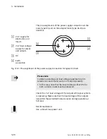
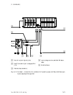
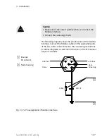
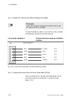
The following diagram shows the pin allocation of the fieldbus
interface. Connect the fieldbus cables to the appropriate pins
of the bus cable socket. Note also the connecting instructions
in further diagrams, as well the instructions in the PLC manual
for your controller.
1
Internal
RCnetwork
2
Node housing
1M
Ω
220nF
GND Bus
+ 24VBus
Data −
Screening
Data +
1
2
Fig.3/15: Pin assignment of fieldbus interface
Содержание IFB11-03
Страница 2: ......
Страница 4: ...Contents and general instructions II Festo P BE VIFB11 03 EN en 0503g...
Страница 18: ...Contents and general instructions XVI Festo P BE VIFB11 03 EN en 0503g...
Страница 19: ...Summary of components 1 1 Festo P BE VIFB11 03 EN en 0503g Chapter 1...
Страница 28: ...1 Summary of components 1 10 Festo P BE VIFB11 03 EN en 0503g...
Страница 29: ...Fitting 2 1 Festo P BE VIFB11 03 EN en 0503g Chapter 2...
Страница 39: ...Installation 3 1 Festo P BE VIFB11 03 EN en 0503g Chapter 3...
Страница 71: ...Commissioning 4 1 Festo P BE VIFB11 03 EN en 0503g Chapter 4...
Страница 89: ...4 Commissioning 4 19 Festo P BE VIFB11 03 EN en 0503g Fig 4 4 I O configuration DLC 100...
Страница 122: ...4 Commissioning 4 52 Festo P BE VIFB11 03 EN en 0503g...
Страница 123: ...Diagnosis and error treatment 5 1 Festo P BE VIFB11 03 EN en 0503g Chapter 5...
Страница 144: ...5 Diagnosis and error treatment 5 22 Festo P BE VIFB11 03 EN en 0503g...
Страница 145: ...Technical appendix A 1 Festo P BE VIFB11 03 EN en 0503g Appendix A...
Страница 159: ...Accessories B 1 Festo P BE VIFB11 03 EN en 0503g Appendix B...
Страница 206: ...B Accessories B 48 Festo P BE VIFB11 03 EN en 0503g...
Страница 207: ...Index C 1 Festo P BE VIFB11 03 EN en 0503g Appendix C...
Страница 208: ...C Index C 2 Festo P BE VIFB11 03 EN en 0503g C Index C 1...
Страница 214: ...C Index C 8 Festo P BE VIFB11 03 EN en 0503g...


