Festo 1501325 Скачать руководство пользователя страница 8

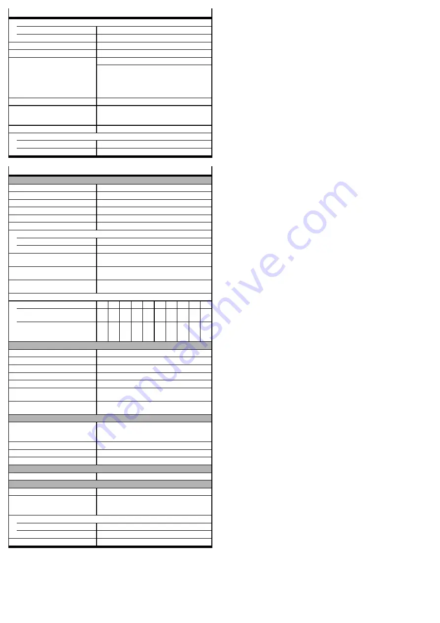
Operating and environmental conditions CMMP-AS-...-M0

Permissible setup altitude above sea level

with rated output

[m]

1000

with power reduction

[m]

1000 … 2000

Air humidity

[%]

0 … 90 (non-condensing)

Protection class

IP20

Degree of contamination in accordance
with EN 61800-5-1

2

The integrated safety equipment requires compliance
with degree of contamination 2 and thus a protected
installation space (IP54). This must always be ensured
through appropriate measures, e.g. through installa-
tion in a control cabinet.

Operating temperature

[°C]

0 … +40

Operating temperature with
power reduction of 2.5 % per
Kelvin

[°C]

+40 … +50

Storage temperature

[°C]

-25 … +70

Vibration and resistance to shocks

Operation

in accordance with EN 61800-5-1, section 5.2.6.4

Transport

in accordance with EN 61800-2, section 4.3.3

Electrical data [X40]

Control ports STO-A, 0V-A / STO-B, 0V-B

Nominal voltage

[V]

24 (related to 0V-A/B)

Voltage range

[V]

19.2 … 28.8

Permissible residual ripple

[%]

2 (related to nominal voltage 24 V)

Overvoltage discharge

[V]

31 (disconnect in case of error)

Nominal current

[mA]

20 (typical; maximum 30)

Starting current

[mA]

450 (typical, duration approx. 2 ms; max. 600 at 28.8 V)

Input voltage threshold

Switching on

[V]

Approx. 18

Switching off

[V]

Approx. 12.5

Switching time from High to
Low (STO-A/B_OFF)

[ms]

10 (typical; maximal 20 at 28.8 V)

Switching time from High to
Low (STO-A/B_ON)

[ms]

1 (typical; maximum 5)

Maximum positive test im-
pulse length at logic 0

[µs]

<

300 (related to nominal voltage 24 V and intervals

>

2 s between impulses)

Switch-off time to power output stage inactive and maximum tolerance time for test impulse

Input voltage (STO-A/B)

[V]

19

20

21

22

23

24

25

26

27

28

Typical switch-off time
(STO-A/B_OFF)

[ms]

4.0

4.5

5.0

6.0

6.5

7.0

7.5

8.0

8.5

9.5

Maximum tolerance time
for test impulse at 24 V
signal

[ms]

<

2.0

<

2.0 2.0

2.5

3.0

3.5

4.5

5.0

5.5

6.0

Feedback contact C1, C2

Design

Relay contact, normally open

Max. voltage

[V DC]

<

30 (overvoltage-proof up to DC 60 V)

Nominal current

[mA]

<

200 (not short-circuit proof )

Voltage drop

[V]

1

Residual current (contact open) [µA]

<

10

Switching time closing
(T_C1/C2_ON)

[ms]

<

(STO-A/B_OFF + 5 ms)

Switching time opening
(T_C1/C2_OFF)

[ms]

<

(STO-A/B_ON + 5 ms)

Auxiliary supply 24V, 0V – output

Design

Logic power supply of the motor controller. Protected
against reverse polarity, overvoltage-proof up
to DC 60 V

Nominal voltage

[V]

24

Nominal current

[mA]

100 (short-circuit proof, max 300 mA)

Voltage drop

[V]

1 (for nominal current)

Galvanic isolation

Galvanically isolated potential areas

STO-A / 0V-A; STO-B / 0V-B; C1 / C2; 24V / 0V

Cabling

Max. cable length

[m]

30

Screening

When wiring outside the control cabinet, use screened
cable. Guide screening into the control cabinet /
attach to the side of the control cabinet.

Cable cross section (flexible conductors, wire end sleeve with insulating collar)

One conductor

mm²

0.25 … 0.5

Two conductors

mm²

2 x 0.25 (with twin wire end sleeves)

Tightening torque M2

[Nm]

0.22 … 0.25

Содержание 1501325

Страница 1: ...ch EN ISO 13849 EN 61800 5 2 Das Sicherheitsmodul erf llt die Anforderungen der Pr fgrundlagen Kategorie 4 PL e nach EN ISO 13849 1 SIL CL 3 nach EN 61800 5 2 EN 62061 IEC 61508 und kann in Anwendunge...

Страница 2: ...demontiert werden 6 Elektrische Installation 6 1 Sicherheitshinweise Bei der Installation m ssen die Anforderungen der EN 60204 1 erf llt werden Warnung Gefahr des elektrischen Schlags bei Spannungsqu...

Страница 3: ...gleiche Nummer werden aber mit vorangestellten und nachgestellten Mittel balken dargestellt z B 1 7 0 In Fig 5 sind die f r die funktionale Sicherheit relevanten Fehlermeldungen aufgelistet Die vollst...

Страница 4: ...ximale positive Testimpuls l nge bei 0 Signal s 300 bezogen auf Nennspannung 24 V und In tervallen 2 s zwischen den Impulsen Abschaltzeit bis Leistungsendstufe inaktiv und maximale Toleranzzeit f r Te...

Страница 5: ...basic test requirements Category 4 PL e in accordance with EN ISO 13849 1 SIL CL 3 in accordance with EN 61800 5 2 EN 62061 IEC 61508 and can be used in applications up to cat 4 PL e in accordance wi...

Страница 6: ...ructions The requirements of EN 60204 1 must be fulfilled during installation Warning Danger of electric shock from voltage sources without protective measures Use only PELV protective extra low volta...

Страница 7: ...sub index y display e g E 5 1 0 Warnings have the same number but are represented with previous and subsequent middle benches e g 1 7 0 Fig 5 lists the error messages that are relevant for functional...

Страница 8: ..._ON ms 1 typical maximum 5 Maximum positive test im pulse length at logic 0 s 300 related to nominal voltage 24 V and intervals 2 s between impulses Switch off time to power output stage inactive and...

Страница 9: ...El m dulo de seguridad cumple los requisitos de los principios de ensayo categor a 4 PL e seg n EN ISO 13849 1 SIL CL 3 seg n EN 61800 5 2 EN 62061 CEI 61508 y puede utilizarse en aplicaciones de has...

Страница 10: ...04 1 Advertencia Peligro de descargas el ctricas en fuentes de tensi n sin medidas de seguridad Para la alimentaci n el ctrica de la l gica utilice exclusivamente circuitos PELV conforme a EN 60204 1...

Страница 11: ...can con E de Error un ndice principal xx y un sub ndice y p ej E 5 1 0 Las advertencias tienen el mismo n mero pero entre guiones p ej 1 7 0 En la Fig 5 figuran los mensajes de error relevantes para l...

Страница 12: ...300 referida a tensi n nominal de 24 V e intervalos 2 s entre los pulsos Tiempo de desconexi n hasta paso de salida de potencia inactivo y tiempo de tolerancia m ximo para pulsos de prueba Tensi n de...

Страница 13: ...de s curit r pond aux exigences des principes de test cat gorie 4 PL e selon EN ISO 13849 1 SIL CL 3 selon EN 61800 5 2 EN 62061 CEI 61508 et peut tre utilis dans des syst mes de cat gorie 4 PL e selo...

Страница 14: ...de la norme EN 60204 1 Avertissement Risque d lectrocution en cas d utilisation de sources d alimentation sans aucune mesure de protection Utiliser exclusivement pour l alimentation logique lectrique...

Страница 15: ...eur et post rieur par ex 1 7 0 Les messages d erreur importants pour la s curit fonctionnelle sont r pertori s dans la Fig 5 La liste compl te des messages d erreur figure dans la documentation Mat ri...

Страница 16: ...s 300 bas e sur une tension nominale de 24 V et des intervalles de 2 s entre les impulsions Temps de coupure jusqu l inactivit de l tage de sortie de puissance et temps de tol rance maximal pour les...

Страница 17: ...dei principi di prova Categoria 4 PL e secondo EN ISO 13849 1 SIL CL 3 secondo EN 61800 5 2 EN 62061 IEC 61508 e pu essere impiegato in applicazioni fino a cat 4 PL e secondo EN ISO 13849 1 e SIL 3 se...

Страница 18: ...04 1 Avvertenza Pericolo di scossa elettrica con fonti di tensione senza misure di sicurezza Per l alimentazione logica elettrica utilizzare esclusivamente circuiti elettrici PELV secondo EN 60204 1 P...

Страница 19: ...o rappresentate precedute e segui te da una barra centrale ad es 1 7 0 Nella Fig 5 sono elencati i messaggi di errore rilevanti per la sicurezza funzionale La lista completa dei messaggi di errore dis...

Страница 20: ...alla tensione nominale 24 V e intervalli 2 s tra gli impulsi Tempo di disattivazione finch il modulo terminale di potenza inattivo e tempo di tolleranza massimo per impulsi di prova Tensione d ingress...

Страница 21: ...2 1 1 1 CMMP AS M0 CMMP AS M0 GDCP CMMP M0 HW 12 1 2 CMMP AS M0 SIL 3 Safe Torque Off STO EN 61800 5 2 EN 62061 IEC 61508 EN ISO 13849 1 4 PL e CMMP AS M0 12 1 3 STO STO Safe Torque Off GDCP CMMP M0...

Страница 22: ...e PELV PELV EN 60204 1 PELV EN 60204 1 PELV IEC EN 60204 1 24 V EN 60204 1 1 5 mm ESD ESD electrostatic discharge ESD 6 2 X40 CMMP AS M0 X40 8 0 V 0 V 7 24 V DC 24 V DC 24 V 6 C2 STO 5 C1 4 0V B 0 V S...

Страница 23: ...0 5 2 SIL3 STO Safe Torque Off EN ISO 13849 1 4 PL e SIL SIL 3 SIL CL 3 Safety Integrity Level EN 61800 5 2 EN 62061 IEC 61508 4 EN ISO 13849 1 PL PL e Performance Level EN ISO 13849 1 DCavg 97 07 Ave...

Страница 24: ...12 5 STO A B_OFF ms 10 28 8 V 20 STO A B_ON ms 1 5 0 s 300 24 V 2 s STO A B V 19 20 21 22 23 24 25 26 27 28 STO A B_OFF ms 4 0 4 5 5 0 6 0 6 5 7 0 7 5 8 0 8 5 9 5 24 V ms 2 0 2 0 2 0 2 5 3 0 3 5 4 5 5...

Отзывы: