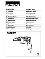
The instructions contained in this manual must be strictly
followed, it should be carefully read and kept close at hand to
use when carrying out maintenance on the indicated parts.
If the tool is used with care and normal maintenance is carried
out, it will work well for a long time.
The functions and use of the tool you have bought shall be
only those described in this manual. Any other use of the tool
is strictly forbidden.
ILLUSTRATIONS
DESCRIPTION (See figures)
A Screwdriver plate (Fig.1)
B Limit of screw depth (Fig.1)
C Adjustment cylinder (Fig.1)
D Belt clip (Fig.1)
E Cooling vent (Fig.1)
F Reverse switch (Fig.1)
G On/Off switch (Fig.1)
H Locking button (Fig.1)
I Electronic speed regulation control (Fig.1)
EQUIPMENT
- Operating instructions
- Safety instructions
- Warranty
BEFORE USING THIS TOOL
Before using the tool, make sure the mains voltage is correct:
it must be the same as that on the specification label.
Machines with 0V can also be connected to a 0-V mains
supply.
Before plugging in the tool, always make sure the control
trigger switch G works properly and returns to the (“OFF”)
position when released.
STARTING THE TOOL
WARNING! Check that the mains voltage is the same as that
in the machine’s specifications.
Plug the machine in with the switch off. Press switch button G
to start the machine and release to stop.
For continuous action, press the switch G and block with
button H.
The machine can be stopped again by pressing and releasing
button G.
Locking the switch is not advisable for precision work.
Electronic speed regulation
These models include the On/Off switch G, a speed regulator
I which permits selection of the speed most
suitable for the specific job.
The required speed is obtained using speed regulator I, to
the left and right as applicable.
Electronic regulation can be carried out with the machine
running.
Changing direction of rotation left/right.
Select direction of rotation with reversing lever F.
Due to a locking mechanism, the reversing switch F can only
be switched when the On-/off switch G is not depressed. Only
activate the F commutation switch with the machine turned
off.
Setting the depth gauge
The C adjustment bushing has 8 positions (0.2 mm/turn) that
allow the choice of screw depth based on the screw head.
Set the C adjustment bushing all the way forward, until
it stops. Set the screw depth by turning the C adjustment
bushing:
To the right = more screw depth.
To the left = less screw depth.
Next, turn the C adjustment bushing all the way back.
The best way to adjust correctly is make a trial screw hole.
The screw is held in place with a universal magnetic
support.
Press the end of the screw firmly against the material to be
screwed until the B depth limit and the screwdriver sheet
disconnect.
To loosen screws, move the F lever to the L position, move it
to the left and remove the B screw depth by tilting it forward.
CHANGING THE PLATE
To change the screwdriver plate A, remove the B screw depth
by tilting it forward.
The pre-selection of the screw depth will be changed and you
will have to readjust the limit.
TECHNICAL DATA
Screwdriver
SDF8/700ER
Input power
W
701
No-load speed
/min
0-000
Electronic / Reversible
Yes
Tool holder capacity inner hexagon
mm
6,5
Max. diameter of the screw
mm
6
Torque speed
Nm
11
Acoustic pressure
dB(A)
8
Sound-power level
dB(A)
95
Vibration acceleration
m/s²
,7
Weightaccording EPTA - Procedure 01/00
Kg
1,8
Содержание SDF8/700ER
Страница 1: ...SDF8 700ER SCREWDRIVER DESTORNILLADOR TOURNEVIS CACCIAVITE SCHRAUBENDREHER CHAVE DE FENDA...
Страница 2: ...A B F I G D E H Fig 1...
Страница 21: ...21...
Страница 23: ...23 B F B A B 8 Felisatti Felisatti...
Страница 25: ...25...
Страница 26: ...26...
Страница 27: ...27...


