


68
AD 951
A 941 / AD 941
"
!
#
#
!"
&
%
$
$
BL
%
)
/
(
0,6 mm
1 x
400060-191
min. 240 mm
#
400060-177
2
4
6
8
0
1
3
5
7
%
400060-157
0˚
22,5˚
40˚
35˚
30˚
25˚
20˚
15˚
10˚
5˚
45˚
0
12
6
m
min
0
400060-140
400060-132
"
&
BL
/
)
(
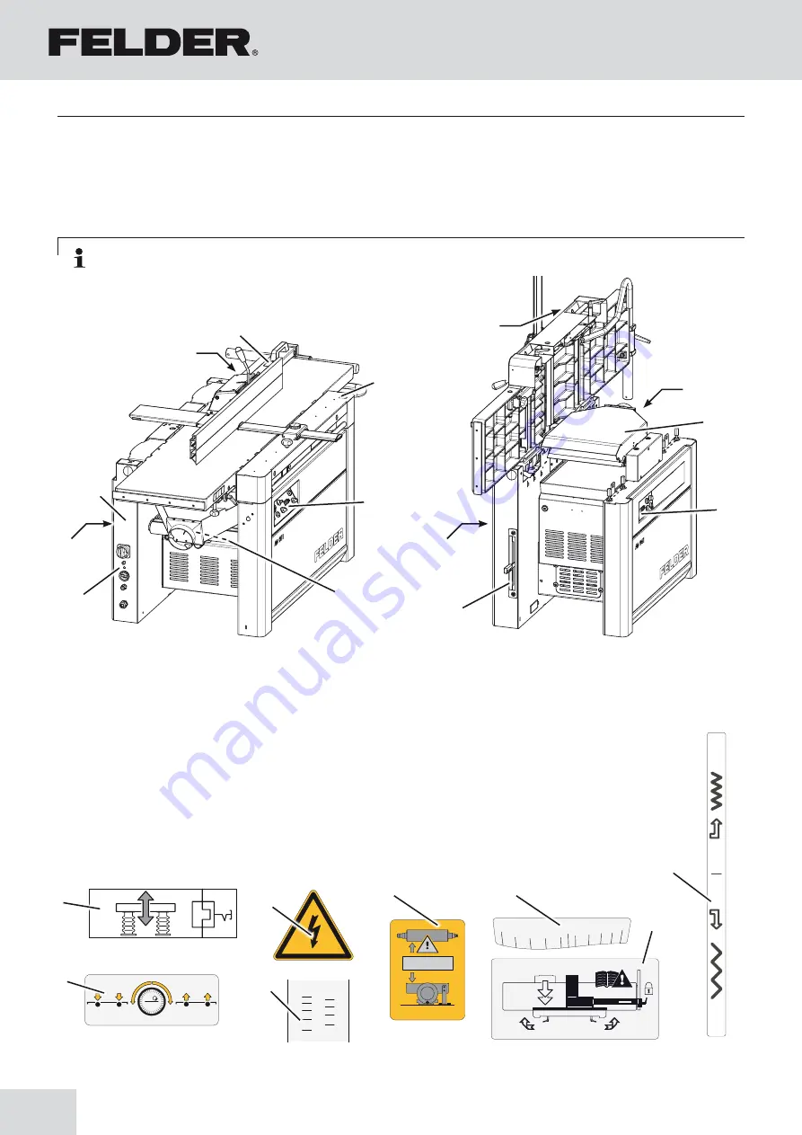
Planer-Thicknesser
A 941 / AD 941 / AD 951
!
Data plate
"
Motor protection switch button
#
Danger! Electric current!
$
Control panel covers (with options)
depending on the equipment - See chapter entitled:
>Operation and display elements<
%
Scale - Bridge guard
&
Scale - Planer fence
/
Adjusting the planer fence
*
Under table rollers (Option)
)
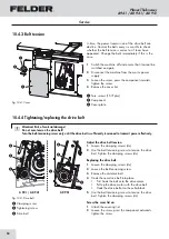
Gear lever (AD 941)
BL
Changeover position
Fig. 12-1: machine base-frame
12.1 Overview - pictograms, signs and labels
Note: All the pictograms, signs and labels affixed to the machine must be kept visible, readable and may not
be removed.
Annex
12 Annex
Содержание AD 941
Страница 13: ...13 Planer Thicknesser A 941 AD 941 AD 951 Safety...
Страница 67: ...67 Planer Thicknesser A 941 AD 941 AD 951 Faults...
Страница 69: ...69 Planer Thicknesser A 941 AD 941 AD 951 Annex...
Страница 70: ......
Страница 71: ......


