background image

62

"

#

!

!

!

Planer-Thicknesser

A 941 / AD 941 / AD 951

11.6.2 Reversing/changing System Tersa automatic cutterblock planer knives

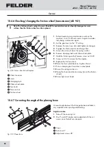
Fig. 11-5: Changing the Tersa reversible knives

Fig. 11-6: Assembling position 

Note: 

Reverse or replace the planer knives once the planing results are no longer satisfactory.

Only use original FELDER planer knives:


See: Tools and Accessories catalogue

Note: 

The planer knives are only properly clamped once a sample workpiece has been planed.

Warning! Risk of injury! The planer knives are razor sharp. 

Handle the planer knives with the utmost care. especially when turning the cutterblock by hand.

Attention! Risk of material damage!

Execute the following instructions exactly!

Attention! Risk of material damage!

Do not clean with compressed air! Ensure that the planer knife is positioned correctly!

1.

  Switch the machine off and ensure that it cannot be 

switched on again.

2.

  Pivot the exhaust hood up

3.

  Using the available brass pin, strike the knife base 

downwards.

4.

  Pull the planer knife sideways out of the cutterblock.

5.

  Clean resin residues thoroughly from the planer 

knife, knife base and cutterblock. Use resin remover 

art. no. 10.0.022 (0,5 l spray bottle) or 10.0.023 

(3,0 l).

6.

  Reverse the planer knife (if only one cutting edge ‘ 

is worn)

7.

  Push the planer knife (reversed or new) again into 

the cutterblock and center.

8.

  Repeat steps 3 to 7 for the other planer knives.

9.

  Prepare the machine for operation and start 

cutterblock.

10.

 Plane sample workpiece. The planer knives are 

clamped automatically by the centrifugal force

!

Brass pin

"

Knife base

#

Planer knife

Faults

Содержание AD 941

Страница 1: ...ion for continual reference Dok ID 432010 903A_02 Englisch 2021 03 16 Operating Manual Planer Thicknesser AD 941 AD 951 Surface planer A 941 GER Original operating manual language Other languages Tran...

Страница 2: ...efore assembly and operation This manual must be kept in good condition and should be considered as part of the machine Furthermore the manual must be kept to hand and within the vicinity of the machi...

Страница 3: ...7 Personal protective equipment 10 2 8 Machine hazards 10 2 9 Other risks 11 2 10 Particle emission 11 2 11 Foreseeable misuse 12 3 Declaration of Conformity 14 4 Technical data 15 4 1 Dimensions and...

Страница 4: ...31 8 1 Safety instructions 31 8 2 Adjusting the chip thickness 31 8 2 1 Adjusting the joint 31 8 3 Adjusting the height of the receiver side of the planer table 32 8 3 1 Check the adjustment with a ga...

Страница 5: ...chain drive 53 10 4 3 Belt tension 54 10 4 4 Tightening replacing the drive belt 54 10 4 5 Tightening replacing the gear belt AD 941 55 10 4 6 Checking changing the friction wheel transmission AD 941...

Страница 6: ...prevention regulations and general safety regulations Before beginning any work on the machine ensure that the manual in particular the chapter entitled Safety and the respective safety guidelines ha...

Страница 7: ...ls may be found on our website www felder group com 1 6 Spare parts If unauthorised spare parts are fitted into the machine all warranty service compensation and liability claims against the manufactu...

Страница 8: ...other than those it was designed for The chapter entitled Safety offers an overview of all the important safety considerations necessary to optimise safety and ensure the safe and trouble free operat...

Страница 9: ...all functions and potential dangers of the machine Spe cialist staff is a term that refers to those who due to their professional training know how experience and knowledge of relevant regulations ar...

Страница 10: ...ne are based on the results of this analysis and correspond to state of the art technology The machine is considered operationally safe when used properly Nevertheless there are some remaining risks t...

Страница 11: ...d woods Risk of injury through being crushed cut caught wound up or sliced 2 9 Other risks Warning Risk of injury Even if the safety measures are complied with there are still certain associated risks...

Страница 12: ...tools and accessories that are not permitted by the manufacturer Use only genuine spare parts supplied by the manufacturer Making changes and modifications to the machine Bridging or adaptation of pr...

Страница 13: ...13 Planer Thicknesser A 941 AD 941 AD 951 Safety...

Страница 14: ...Design Test Certificate No HO 201009 AD 941 AD 951 HO 201003 A 941 Planer Thicknesser AD 941 AD 951 Surface planer A 941 Declaration of Conformity Note Machine number The machine number of this machi...

Страница 15: ...al height C1 Thickness planing 1510 mm 1650 mm Overall width D Max 1360 mm Max 1480 mm total length E 2360 mm 2400 mm Net weight 610 kg 900 kg Operating room temperature 10 to 40 C 10 to 40 C Machine...

Страница 16: ...1080 mm 1095 mm Total planer table length 2200 mm 2252 mm Surface planing width 410 mm 510 mm Planer fence tiltable from 90 to 45 90 to 45 Fence guide 170 x 1300 mm 170 x 1300 mm Depth of cut Max 5 mm...

Страница 17: ...eed to be imple mented Factors which can significantly affect the emis sion level that presently exists at the workplace include duration of the effect characteristics of the workspace and other ambie...

Страница 18: ...laner unit Cutterblock Cutterblock cover Planer fence Adjusting the depth of cut Dust extraction outlet Control panel Potential free contact Operating hour meter Option BLMain switch BMWorkpiece rolle...

Страница 19: ...that switches the machine off in the event of an overload 3 AD 951 Safety regulations The machine is equipped with emergency stop buttons They must be unlocked before the machine can be started EMERGE...

Страница 20: ...and outfeed rollers Rubber in and outfeed rollers ensure that thin workpiec es can be easily handled Changing rubber in and outfeed rollers See chapter entitled Maintenance and servicing 5 4 Automati...

Страница 21: ...5 9 Table extensions with F Coupling Note For further accessories and dust extraction equipment see Accessory catalogue 5 7 Workpiece roller Under table rollers optional Fig 5 8 Workpiece roller Under...

Страница 22: ...machine as carefully as possible in order to prevent damage Avoid subjecting the machine to shocks When transporting the machine overseas ensure that the packaging is airtight and that a desiccant is...

Страница 23: ...ls or separating them according to type and size for recycling Note help preserve the environment Packaging materials are valuable raw materials and in many cases they can be used again or expediently...

Страница 24: ...pallet jack bolt the transportation device option onto the housing 2 Consider the centre of gravity when hoisting the machine danger of overturning 3 Unload the machine from the pallet with the fork...

Страница 25: ...d storage Installation site requirements Operation room temperature 10 to 40 C Ensure that the work surface is sufficiently stable and has the proper load bearing capacity Provide sufficient light at...

Страница 26: ...nt damage For this reason this work may only be carried out by authorised trained personnel who are familiar with how to operate the machine and in strict observance of all safety instructions Ensure...

Страница 27: ...feeding surface pla ner table 2 Mount the rear cutterblock cover Cover insert into the combination fence Clamping screw tighten Planer fence Cover Clamping screw Screw in Bolt in Bar and counter it w...

Страница 28: ...table with screws and washers 2 Subsequently set the height of the workpiece roller with an even workpiece 3 Tighten the screws once the angularity is set screw locking nut Shim Ball socket 1 Ball so...

Страница 29: ...d an air speed of 20 m s at the connector see Technical data Check the air speed before putting the machine into operation for the first time and after essential changes The dust extractor setup must...

Страница 30: ...priate socket for a three phase alternating current motor CEE Electrical connection requirements The machine must be earthed with electrical conductors The voltage fluctuations in the mains supply may...

Страница 31: ...Type of wood hardwood or softwood Wood dampness Feed rate Cutterblock 2 or 4 Cutterblock Possibilities Cutterblock Possibilities SS HS HW The motor power of your machine The depth of cut is adjusted...

Страница 32: ...aner table is reached 3 Tighten the lock nut 8 3 Adjusting the height of the receiver side of the planer table 1 Prepare the gauge as shown in the illustration opposi te 2 Set the gauge on the receive...

Страница 33: ...move fence 8 5 Retooling from a planer to a thicknesser Fig 8 5 Planer table Proceed in reverse order when closing the joiner tables Ensure that the planing table is at least 240 mm below the planing...

Страница 34: ...thread clearance adjust the thicknessing table from bottom to top The maximum depth of cut is directly related to the following factors Workpiece width Type of wood hardwood or softwood Wood dampness...

Страница 35: ...he planer table height using key in steps of 0 1 mm 0 005 To move use the quick motion use switch Calibration of control unit Move the thicknesser table to 20 mm 0 790 position using a test piece Pres...

Страница 36: ...ted as the actual value Actual value display Desired value display Start a position duty Stop a position duty delete error codes Delete the last input Long operation Switch over between parametric lev...

Страница 37: ...ed value 1 2 3 or 4 5 6 Press the Start key to start positioning The thicknesser table travels the distance of the saved value 1 2 3 or travels to the saved position 4 5 6 Press F key for about 5 seco...

Страница 38: ...ess the Start key to start positioning 8 9 7 Conversion mm inch The thicknesser table moves according to the given value The control mechanism remains in the incremental mode until the ABS INC key is...

Страница 39: ...not calibrated block Calibration of control unit Motor defect Please contact customer service Soiled mechanics Thicknesser table height spindles and chain drive Cleaning Lubrication See chapter entit...

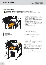
Страница 40: ...orkpieces that can be safely placed on the machine and guided Carefully inspect workpieces for foreign matter nails screws which might impair processing Ensure that the tool turns freely Ensure the cu...

Страница 41: ...Y STOP button depending on the equip ment Gear lever AD 941 9 2 Switching on the machine Switching off the machine Attention Risk of material damage If the machine will not be used for a longer period...

Страница 42: ...ery warped Rabbet planing at the end of the cutterblock Only the following working techniques are permitted with the planer unit Planing the wide side of a workpiece Joining the narrow side of a workp...

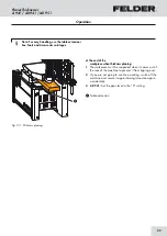
Страница 43: ...ure that your hands are placed on the workpiece in a closed position with the thumbs against the closed hands 9 4 2 General procedures for authorised working techniques 1 Switch the machine off before...

Страница 44: ...ng small workpieces use pushing strips and a push block Use an auxiliary fence with the minimum measurements to guide the workpiece safely Width B min 60 mm 9 4 4 Jointing Fig 9 5 Jointing 1 Take note...

Страница 45: ...ntinue as described in the Jointing section Tapering beveling small workpieces You must always use a special jig for beveling small narrow workpieces This device can also be used to bevel long workpie...

Страница 46: ...e must be fitted with a connected CEE coupling 9 4 7 Using the power feeder on the surface planer Fig 9 8 Using a power feeder The power feeder is mounted onto the machine frame This will provide grea...

Страница 47: ...on cuts the workpiece is not worked over its entire length Attention Risk of material damage When working on 2 workpieces simultaneously their thickness may not differ by more than 1 mm Width max 404...

Страница 48: ...rkpiece Place the surface planed side of the workpiece on the thicknesser table and push into the machine until it is drawn in by the feed rollers Infeed roller standard A maximum of 2 workpieces can...

Страница 49: ...ar of the machine to prevent it from tipping over 2 If you are not going to continue working switch off the machine and secure it against being turned on again accidentally 3 AD 941 Set the gear lever...

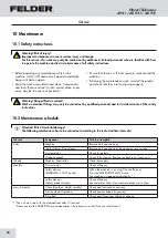
Страница 50: ...KG service department if problems or a fault function should occur 10 Maintenance 10 1 Safety instructions 10 2 Maintenance schedule Service Attention Risk of material damage The following maintenance...

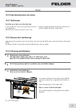
Страница 51: ...tension is factory set to the ideal value In time the belt can stretch causing the power transmissi on to deteriorate The belt tension must be corrected in such a case Replace the appropriate belt im...

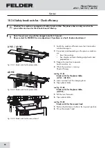
Страница 52: ...r tables are closed or the extractor hood is tilted up 1 Switch the machine off and ensure that it cannot be switched on again 2 If required and depending on the previous machine use Reset the machine...

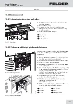
Страница 53: ...ion the thicknesser table in the top most position see thicknesser table height adjustment 2 Disconnect the machine from the mains power supply 3 Loosen the screws Remove the cover 4 Remove dust and c...

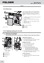
Страница 54: ...elt Tighten the clamping screws 4x Replacing the drive belt 1 Loosen the clamping screws 4x 2 Loosen the belt tensioning screw 3 Remove the old drive belt 4 Hook the new drive belt into place First ho...

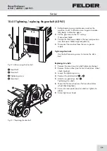
Страница 55: ...ing screw to tension the drive belt Replacing drive belts 1 Remove the cover see drive belt tighten exchange 2 Remove friction wheel see friction wheel drive wheel check replace 3 Loosen the tightenin...

Страница 56: ...on Tighten the nut 11 Put on clamping bush and chain wheel plate 12 Screw the spring washer on 13 Hang the chain and check running turn at the friction wheel 14 Screw tight cover hood Fig 10 8 Frictio...

Страница 57: ...the front 7 To reassemble follow the instructions in the reverse order Sprocket wheels Bearing block cover plate Adjustment screws Springs Pressure bushings Distance Note The rubber infeed and outfee...

Страница 58: ...t to do after rectifying the fault Before switching the machine back on the fault and its cause are professionally repaired all safety equipment has been assembled according to regulations and is work...

Страница 59: ...of cut Adjusting the joint Replace the planer knives 1 The planer fence angle is not correct Angle setting misadjusted Correcting the angle of the planing fence Unsatisfactory planing result Planer k...

Страница 60: ...side of the planer table It may be necessary to readjust the joint if the planer knives have been changed or replaced See chapter entitled Making adjustments and prepara tions 11 6 Resharpen or replac...

Страница 61: ...ean with compressed air Ensure that the planer knife is positioned correctly 1 Switch the machine off and ensure that it cannot be switched on again 2 Pivot the exhaust hood up 3 Release all the blade...

Страница 62: ...Attention Risk of material damage Do not clean with compressed air Ensure that the planer knife is positioned correctly 1 Switch the machine off and ensure that it cannot be switched on again 2 Pivot...

Страница 63: ...e blade holder and planer blades Repeat this process with all blades 4 Clean the planer blades blade holders and cutterblock of traces of resin as thoroughly as possible do not clean with compressed a...

Страница 64: ...rectly before switching on the machine The operation of the silent power cutterblock is only allowed if ALL pockets are equipped with carbide inserts Check the carbide inserts and clamping screws for...

Страница 65: ...n remover It is recommended to use a small cleaning brush toothbrush or a cotton swab 4 Clean carbide insert thoroughly with a suitable cleaning agent eg resin remover take care of the built up cuttin...

Страница 66: ...7 Changing one single carbide insert All carbide inserts should be changed or turned to the next mark simultaneously 8 Changing or turning just only one of the carbide inserts because of damage may cr...

Страница 67: ...67 Planer Thicknesser A 941 AD 941 AD 951 Faults...

Страница 68: ...lectric current Control panel covers with options depending on the equipment See chapter entitled Operation and display elements Scale Bridge guard Scale Planer fence Adjusting the planer fence Under...

Страница 69: ...69 Planer Thicknesser A 941 AD 941 AD 951 Annex...

Страница 70: ......

Страница 71: ......

Страница 72: ...FELDER KG KR Felder Stra e 1 6060 Hall in Tirol AUSTRIA Tel 43 0 5223 58 50 0 Fax 43 0 5223 56 13 0 info felder group com www felder group com...

Отзывы: