29
!
$
!
#
"
Ø 120 mm - A 941 / AD 941
Ø 140 mm - AD 951
Planer-Thicknesser
A 941 / AD 941 / AD 951
Setup and installation
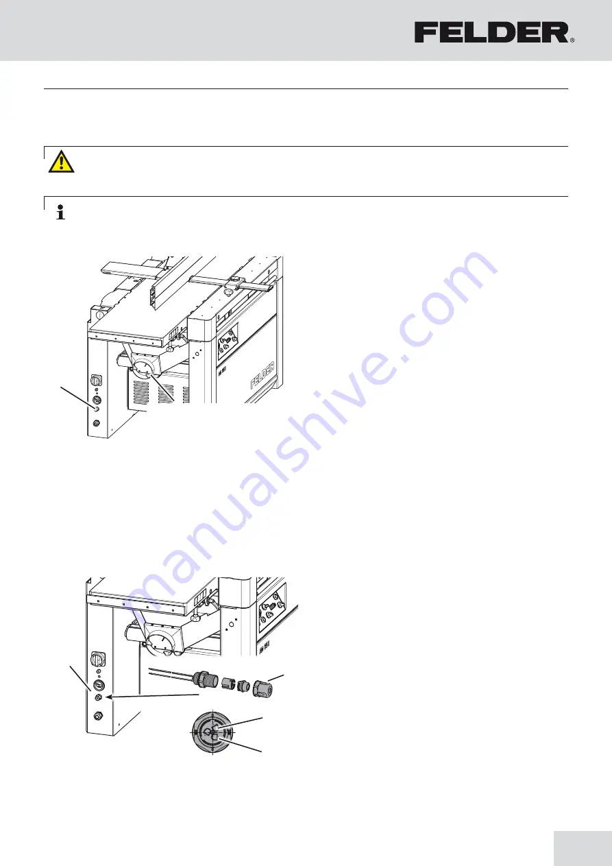
Fig. 7-9: Potential-free contact
Fig. 7-8: Connectors/Dust extraction port dia
7.9 Potential-free contact
7.8 Dust extraction
!
Potential-free contact
Connection to the dust extractor system:
The unit can be connected via the potential-free contact
as follows:
• Cut the wires to the same length.
• Insert into the holes 1 and 2 and push the plugs to-
gether.
• Screw on the plug‘s thumb screw.
• The wires are automatically electrically connected via
an insulation displacement connector.
!
Hole 1
"
Hole 2
#
Thumb screw
$
Potential-free contact
• In addition, the vacuum performance must be sufficient
to achieve the required negative pressures and an air
speed of 20 m/s at the connector. (see “Technical
data”)
• Check the air speed before putting the machine into
operation for the first time and after essential changes.
• The dust extractor setup must be controlled before the
machine is put into operation for the first time. Check for
obvious defects on a daily basis and the efficiency on a
monthly basis.
• The dust extractor must be connected to the machine
in such a manner that it runs in unison with the
machine.
• The dust extraction hoses must be electrically conduc-
tive and grounded to prevent electrostatic
build up.
• Use dust extractors with reduced dust emission to clean
dust from the machine.
Note: As a rule, all units must be vacuumed during use. A time delayed socket is available as an accessory.
Warning! Risk of injury! The dust extraction hose must be non-flammable and must not conduct electricity! For
this reason, only use genuine FELDER dust extraction hoses!
Содержание AD 941
Страница 13: ...13 Planer Thicknesser A 941 AD 941 AD 951 Safety...
Страница 67: ...67 Planer Thicknesser A 941 AD 941 AD 951 Faults...
Страница 69: ...69 Planer Thicknesser A 941 AD 941 AD 951 Annex...
Страница 70: ......
Страница 71: ......


