

INSTRUCTION, USE
AND MAINTENANCE MANUAL
GB
Page 21 of 168
7522-M001-14_P
GG40256.11SL - GG40256.11ST - GG40256.15
GG40256T.15 - GG40256A.15 - GG40256D.15
GG40256TD.15 - GG40256.15SL - GG60360.15
GG60360T.15 - GG60360A.15 - GG60360D.15 - GG60360TD.15
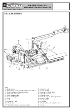
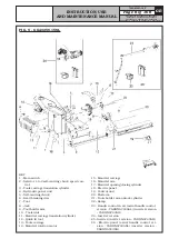
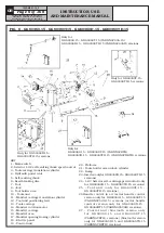
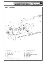
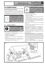
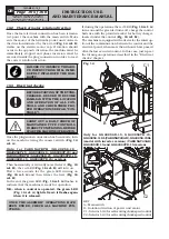
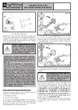
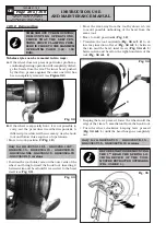
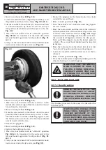
11.2 Control device with bluetooth transmis-
sion (optional)
The control (handle control) can be moved according
to the positioning necessities of the operator.
The operator should place the control in a zone free
from obstacles in order to see clearly and completely
the operative zone.
MAKE SURE THERE ARE NO PER-
SONS OR OBJECTS HIDDEN TO
THE OPERATOR VISUAL FIELD
BY THE WHEEL SIDE PLAY (ESPE-
CIALLY IN CASE OF WHEELS WITH
LARGE DIMENSIONS).
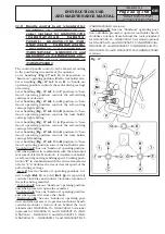
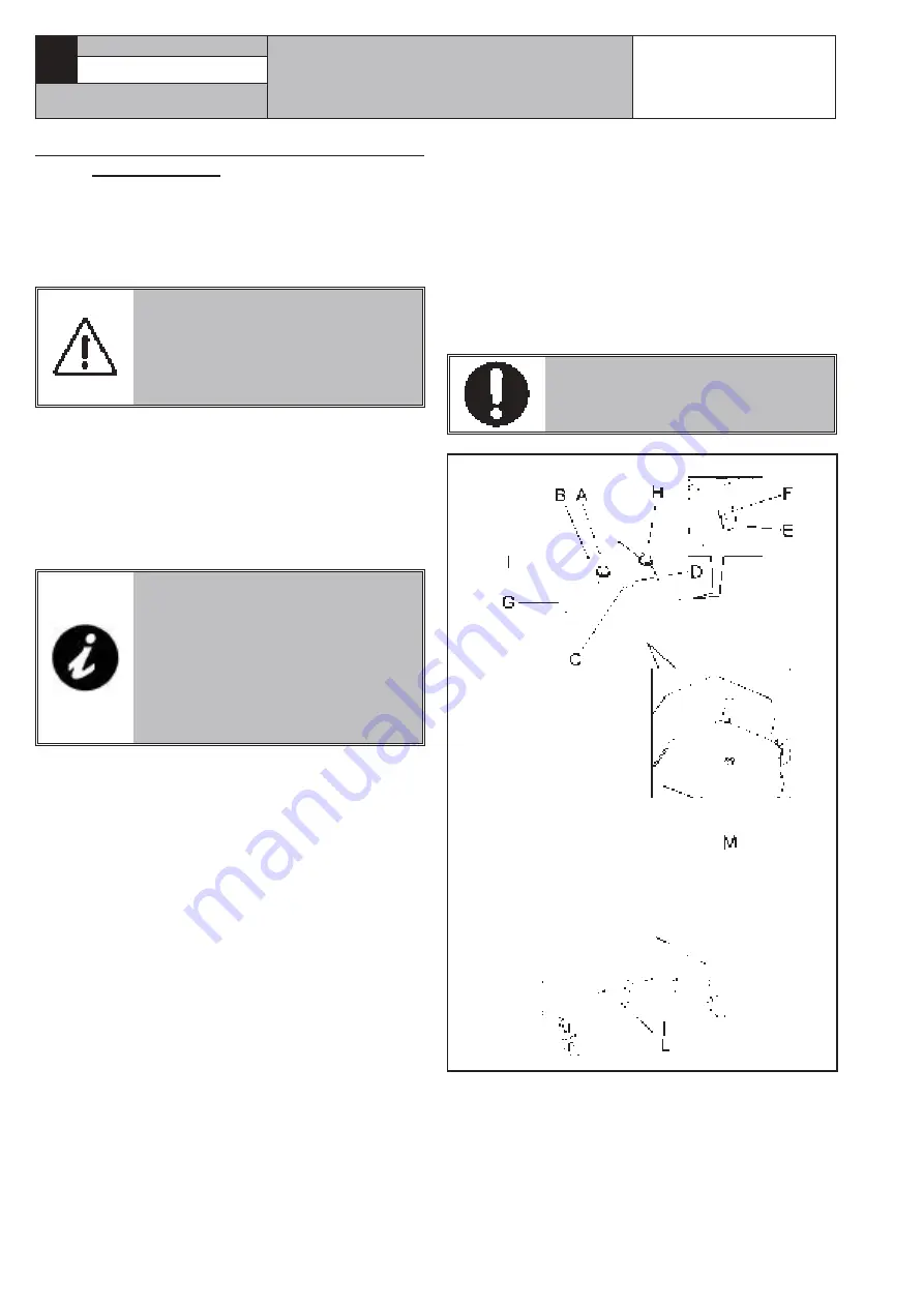
The flashing green led “
A
”, indicates the machine
stand-by position. When any control is operated, the
machine is started and it is ready for operation. During
functioning, the led “
A
” is turned on with a fixed light.
The red turned on led “
B
” and the green turned off
led “
A
” indicate that the manipulator batteries are
exhausted: in order to carry on the functioning, the
batteries must be charged.
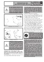
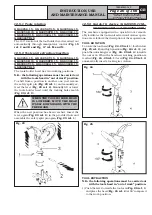
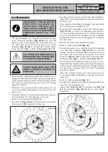
IN ORDER TO ACTIVATE THE COM-
MUNICATION BETWEEN HANDLE
CONTROL AND MACHINE, ON MA-
CHINE SWITCHING AND AFTER
EACH POSITIONING IN STAND-BY
MODE, IT'S NECESSARY TO OPE-
RATE ANY JOYSTICK (LEVER “H”
OR LEVER “I”) FOR 5 SECONDS
AT LEAST.
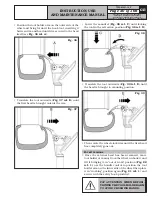
“Push button
C
” has a maintained control position, and
when pressed it rotates the tool holder head counter-
clockwise (from behind the tool).
“Push button
D
” has a maintained control position, and
when pressed it rotates the tool holder head clockwise
(from behind the tool).
“Push-button
E
” has a maintained control position,
and when pressed, it operates the self-centring chuck
opening.
“Push-button
F
” has a maintained control position,
and when pressed it operates the self-centring chuck
closing.
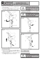
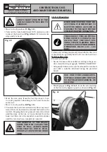
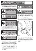
“Button
G
” has one “hands-on” operating position:
when it is pressed and lever “
I
” or “
H
” is laterally
shifted at the same time, it doubles the translation
speed of the self-centring carriage and of the tool holder
carriage respectively.
“Lever
H
” has four maintained control positions:
- Lever rightwards or leftwards, operates respectively
the tool holder carriage shifting rightwards or lef-
twards.
- Lever upwards or downwards: it respectively lowers
or lifts the tool holder arm.
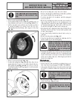
“Lever
I
” has four maintained control positions:
- Lever rightwards or leftwards, operates respectively
the mandrel holder carriage shifting rightwards or
leftwards.
- Lever upwards or downwards: it operates respectively
the rising and the lowering of the mandrel holding
arm.
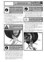
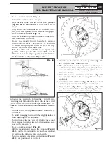
“Pedal
L
” starts clockwise and anti-clockwise rotation
of the mandrel.
When any control is operated, the machine is started
again, ready for operation: led “
A
” flashes.
THE HANDLE MUST NOT BE PLA-
CED WHERE WATER STAGNATES.
Fig. 16


