INSTRUCTION, USE
AND MAINTENANCE MANUAL
GB
Page 24 of 168
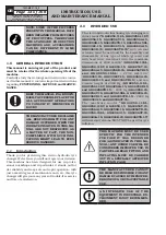
DO NOT CHANGE THE SET OPE-
RATING PRESSURE VALUE BY ME-
ANS OF THE MAXIMUM PRESSURE
VALVES. THE MANUFACTURER
SHALL NOT BE RESPONSIBLE
FOR INJURY OR DAMAGE ARISING
FROM UNAUTHORISED CHANGES.
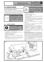
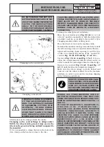
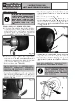
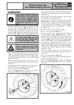
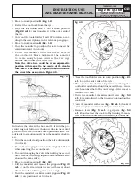
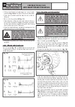
Fig. 18
Clamping on the central hole
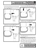
Fig. 19
Clamping on bead seat
OPENING/CLOSING MOVEMENT
OF THE SELF-CENTRING MAN-
DREL CAN GENERATE DANGER
OF SQUASHING, CUTTING, COM-
PRESSING. DURING WHEEL
LOCKING/UNLOCKING PHASE,
AVOID THAT PARTS OF HUMAN
BODY COME INTO CONTACT WITH
MOVING PARTS OF THE MACHINE.
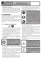
All wheels must be clamped from the inside.
Clamping on the central flange is always safest.
NOTE: for wheels with grooved rims secure the
wheel so the groove is facing outward compared to
the mandrel.
If it is not possible to clamp the rim in the hole of the
disc, clamp on the bead seat close to the disc.
7522-M001-14_P
GG40256.11SL - GG40256.11ST - GG40256.15
GG40256T.15 - GG40256A.15 - GG40256D.15
GG40256TD.15 - GG40256.15SL - GG60360.15
GG60360T.15 - GG60360A.15 - GG60360D.15 - GG60360TD.15
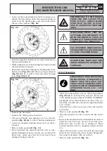
TO SECURE WHEELS WITH ALLOY RIMS ADDI-
TIONAL PROTECTIVE JAWS ARE AVAILABLE.
THEY ALLOW YOU TO WORK ON THE RIMS
WITHOUT DAMAGING THEM. THE PROTECTI-
VE JAWS ARE FITTED ONTO THE MANDREL’S
NORMAL JAWS BY MEANS OF A BAYONET
CONNECTION.
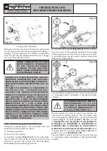
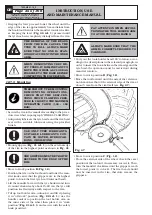
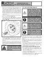
To clamp the wheel proceed as follows:
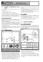
- Move the tool holder arm (
Fig. 22 ref. 1
) to “out
of work” position, manually or with the help of the
provided controls, according to the model of tyre
changing machine which is being used;
- Place the wheel vertical on the machine table;
- Translate the mandrel carriage towards the tyre until
the self-centring arms are inserted inside the rim;
- Adjust self-centring chuck opening to suit the type
of rim to be clamped by means of the “open/close”
control (
Fig. 15 ref.
E/F and Fig.
17 ref.
I/L
);
- Use lever (
Fig. 15 ref. A and Fig. 17 ref. 1
) to po-
sition the coaxial mandrel with the wheel centre, in
order to make the jaws edges skim the wheel edge;
- Operate the control (
Fig. 15 ref. E and Fig. 17
ref. I
) until the wheel is completely clamped;
- Make sure the rim is always correctly locked and
centred, and the wheel is lifted from the machine
platform, in order to prevent the rim from slipping
in the following operations.
KEEP ON OPERATING RIM CLAM-
PING CONTROL, UNTIL REACHING
THE MAXIMUM OPERATING PRES-
SURE (160÷180 BAR), WHICH CAN
BE CHECKED THROUGH THE PRE-
ARRANGED PRESSURE GAUGE.
DURING ALL TYRES MOUNTING AND DE-
MOUNTING OPERATIONS, THE SELF-CEN-
TRING CHUCK ROTATION SPEED CAN BE DOU-
BLED BY ROTATING THE SELECTOR (FIG. 14
REF. C1).
IN CASE OF GG40256D.15, GG40256TD.15,
G G 4 0 2 5 6 . 1 1 S L ( V A R G N A V 4 3 A D ) ,
GG40256.15SL (MODEL WITH INVERTER
VERSION) (VARGNAV43AD) GG60360D.15
AND GG60360TD.15 MODELS, USING THE
SELECTOR (FIG. 14 REF. C2), SELF-CENTRING
CHUCK ROTATION SPEED CAN BE ADJUSTED
RESPECTIVELY AT 1, 6 OR 12 RPM. LOW
SPEED IS RECOMMENDED FOR WHEELS WITH
GREAT DIAMETER AND WEIGHT. 1 RPM IS THE
CORRECT SPEED VALUE FOR THE GROOVE OF
TRUCK TYRES. LUBRICATE THE TYRE BEADS
CAREFULLY TO PROTECT THEM AGAINST
ANY DAMAGE AND SIMPLIFY MOUNTING AND
DEMOUNTING OPERATIONS.

