INSTRUCTION, USE
AND MAINTENANCE MANUAL
GB
Page 38 of 168
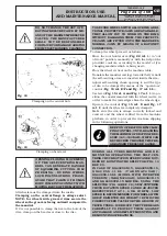
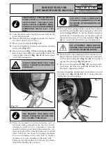
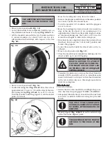
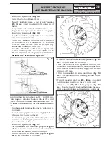
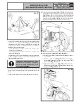
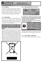
• Carry out the tools holder head 180° rotation accor-
ding to the description of the relevant paragraph, in
order to let the beading disc come into contact with
the tyre outer side (see
Fig. 54
).
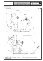
Fig. 54
• Turn the mandrel and smear the entire bead seat of
the rim with lubricant.
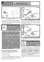
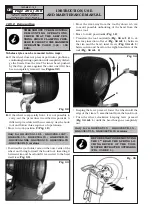
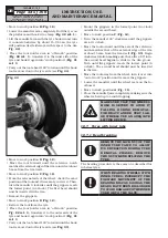
• While doing this, jerk the beading disc forward until
the first bead is removed;
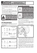
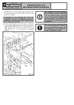
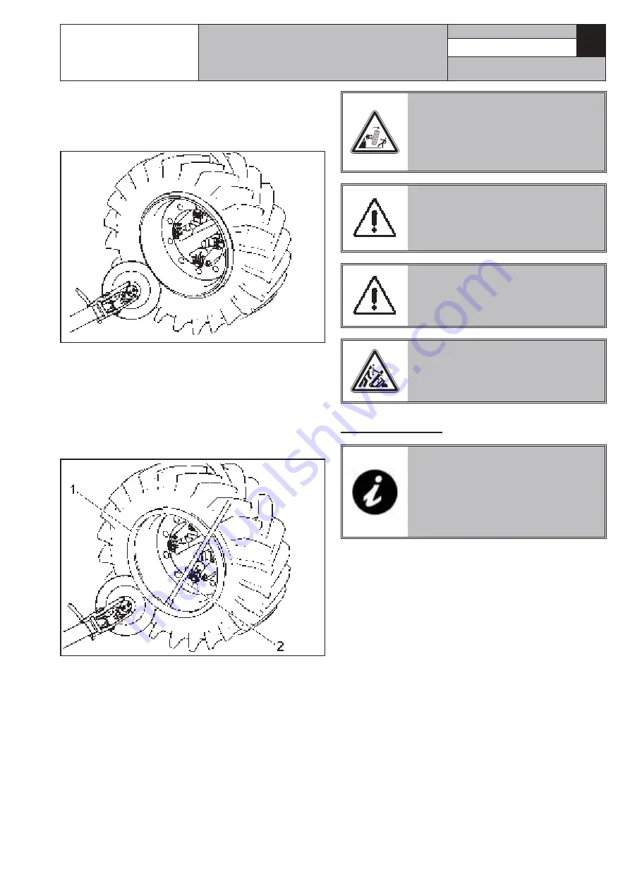
• Repeat the operation, making the beading disc move
forward (see
Fig. 55
) until the stop ring is released
(
Fig. 55 ref. 1
). It will be then extracted through
lever (
Fig. 55 ref. 2
).
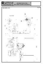
Fig. 55
• Remove the bead wire.
• Remove the O-Ring, when featured.
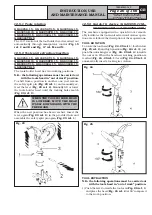
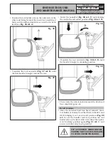
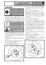
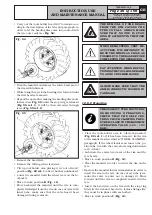
• Tilt up tool holder arm placing it in “out of work”
position (
Fig. 22 ref. 1
) after it has been unhooked.
• Lower the mandrel until the wheel rests on the fo-
otboard.
• Move to work position
B
(
Fig. 12
).
• Move backward the mandrel until the tyre is com-
pletely dislodged from the rim (in case of tyres with
inner tube, make sure that the valve hasn’t been
damaged during removal).
THE REMOVAL OF THE BEADS
FROM THE RIM CAUSES THE
TYRE TO FALL. ALWAYS MAKE
SURE THAT NO ONE IS STAN-
DING BY ACCIDENT IN THE WORK
AREA.
WHEN DEMOUNTING VERY HE-
AVY TYRES, IT IS IMPORTANT TO
MOVE THE WHEEL AS CLOSE AS
POSSIBLE TO THE BASE BEFORE
COMPLETING THE OPERATION.
PAY ATTENTION WHEN REPOSI-
TIONING THE TOOL HOLDER ARM
TO AVOID CRUSHING HANDS.
ALWAYS MAKE SURE THAT THE
ARM IS CORRECTLY HOOKED TO
CARRIAGE.
12.8.2 Mounting
THROUGHOUT TYRE MOUNTING/
DEMOUNTING OPERATIONS,
CHECK THAT THE SELF-CEN-
TRING CHUCK CLAMPING PRES-
SURE IS CLOSE TO THE MAXIMUM
OPERATING VALUE (160 - 180
BAR).
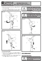
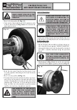
• Place the tools holder arm in “off-work position”
(
Fig. 22 ref. 1
); if it has been removed, fix the rim
to the mandrel as described in “WHEEL CLAMPING”
paragraph. If the wheel features an inner tube, po-
sition the rim with the valve slot facing downwards
(at 6 o’clock).
• Lubricate the entire bead seat of the rim and the
tyre beads.
• Move to work position
B
(
Fig. 12
).
• Place the mandrel in order to centre the rim on the
tyre.
• Operate the mandrel forward translation in order to
insert the rim in the tyre (in case of air tube tyres,
make the valve re-enter not to damage it). Move
forward until the rim is completely inserted in the
tyre.
• Insert the bead wire on the rim with the stop ring
fitted (if the rim and bead wire feature fixing slits,
they must be in phase with each other).
• Move to work position
C
(
Fig. 12
).
7522-M001-14_P
GG40256.11SL - GG40256.11ST - GG40256.15
GG40256T.15 - GG40256A.15 - GG40256D.15
GG40256TD.15 - GG40256.15SL - GG60360.15
GG60360T.15 - GG60360A.15 - GG60360D.15 - GG60360TD.15

