


Rev.06
96/226
7.
COMMUNICATION AND HMI
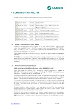
The SIL-D relay is equipped with the following communications ports:
1 LOCAL (front)
RS232
Modbus RTU
2 REMOTE (rear)
RS485
Modbus RTU or IEC 60870-5-103 (by
general settings)
3 REMOTE (rear)
RJ45
IEC 61850 (Depending on model)
4 REMOTE (rear)
RJ45
DNP 3.0 (Depending on model)
5 REMOTE (rear)
RJ45
IEC60870-5-104 (Depending on model)
6 REMOTE (rear)
RJ45
Modbus TCP/IP (Depending on model)
7.1.
Local communication port. RS232
The RS232 communications port is installed on the front of the equipment. The connector
that is used is a DB-9 female
– DCE. The protocol that is used is Modbus RTU (19200 -
8bit
– no parity – 1 stop bit). The protocol map and documentation that are used are
attached in an appendix to this manual.
The PC earth should be connected to the same earth as the relay to avoid communication
problems.
The RS232 communication is fitted with auxiliary voltage insulation, but no insulation with
regards to the relay processors. Therefore, the connection cable between the pc and relay
must not be very long so as to prevent possible electromagnetic interferences with the
equipment.
7.2.
Remote communications port
SIL-D with 1 port RS485 for ModBus or for IEC60870-5-103
In this case, there are 1 RS485 port, it is possible to select ModBus RTU protocol or
IEC60870-5-103 protocol thanks to the general settings.The RS485 port output has two
terminals (+,-), located on the rear of the equipment.
This port can be used to continuously monitor the equipment from a remote PC or SCADA
system. Up to 32 relays can be connected to one bus; each device with a different modbus
address. The equipment modbus address can be configured using the SIcom program.
To minimise communication errors as a result of noise, the use of a stranded and shielded
cable is recommended for the physical connection. All of the + terminals on one side, and
all of the - terminals on the other must be connected together in order to make the
connection.
Resistors should be used at each end if very long cables are used. The best solution for
avoiding reflection is to install resistors at both ends of the cable. The ohm value of these
resistors must be equal to the cable impedance value.
The RS485 communications are fitted with auxiliary voltage insulation, but no insulation
between the various RS485 communication connectors. Fiber optics can be used in very
aggressive environments, and they are connected by using the corresponding converters.
Содержание SIL-D00
Страница 8: ...www fanox com Rev 06 8 226 2 DIMENSIONS AND CONNECTION DIAGRAMS 2 1 Equipment front view...
Страница 9: ...www fanox com Rev 06 9 226 2 2 Equipment dimensions...
Страница 10: ...www fanox com Rev 06 10 226 2 3 Cut out pattern...
Страница 12: ...www fanox com Rev 06 12 226 Digital connections Only as an example...
Страница 13: ...www fanox com Rev 06 13 226 2 5 Terminals...
Страница 49: ...www fanox com Rev 06 49 226...
Страница 50: ...www fanox com Rev 06 50 226...
Страница 51: ...www fanox com Rev 06 51 226...
Страница 52: ...www fanox com Rev 06 52 226...
Страница 111: ...www fanox com Rev 06 111 226 I C 3 7 0 00 A C I N 4 7 0 00 A C V R 5 7 0 00 V D Ang 6 7 0 00 deg C IMax 7 7 0 00 A...
Страница 200: ...www fanox com Rev 06 200 226...
Страница 224: ...www fanox com Rev 06 224 226 14 9 Comments Person in charge of commissioning Date Maintenance performed on the by...
Страница 225: ...www fanox com Rev 06 225 226 NOTES...
Страница 226: ...www fanox com Rev 06 226 226...