


Rev.06
165/226
8.
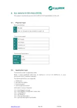
MODBUS RTU PROTOCOL
Communication parameters are:
•
Address and Baudrate
•
8 data bit
•
No parity
•
1 stop bit.
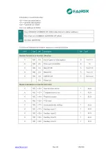
This document describes the steps to follow to read and write data on the SIL-V relay, as
per the ModBUS/RTU protocol. This memory map is only valid for one piece of equipment
and one version of the memory. The positions of existing objects in the memory remain
fixed from one version to the next, but new objects will naturally have new addresses
which will, in turn, remain fixed in future versions. The memory map is described further
on.
The standard ModBUS/RTU protocol is used, so any program or PC can communicate
easily with the equipment.
The SIL-V always acts as a slave, which means that it never initiates communications. The
master is always responsible for initiating communications.
Only a subset of the ModBUS/RTU functions is implemented:
•
Reading function 3.
•
Writing function 16.
The ModBUS/RTU protocol is independent from the hardware. Therefore, the physical
layer can exist in different hardware configurations: RS232, RS485, fibre optic or Ethernet.
Specifically, the relay has a front RS232 port and, as an option, a rear RS485 port. The
data stream in any of the configurations is “half-duplex”.
Each byte of data is transmitted asynchronously and is made up of: 1 start bit, 8 data bits,
1 stop bit and 1 parity bit, if this is how it is programmed. Therefore, the data has 10 or 11
bits, depending on whether or not it includes parity.
If the relay only offers with Modbus RTU the front port, the address (1 to 247) is
configurable but the rest of the paarmeters are fixed and equal to: baudrate 19200, No
parity and stop bit 1.
If the relay offers RS485 modbus RTU protocol the the address (1 to 247) and the
baudrate (4800, 9600, 19200 or 38400) con be but the rest of the parameters are fixed:
without parity and with 1 stop bit.
The master must know the address of the slave that it is going to communicate with. No
unit will act on requests from the master if the message is not addressed to them. The
exception is when the 0 addr
ess, or “broadcast” address, is used, in which case the relay
will act but will not send an answer of any type.
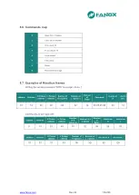
Communications are made in packages or frames, which are groups of data that are sent
asynchronously. The master transmits a frame to the slave, and the slave then replies with
another frame (except in the case of “broadcast” messages).
The end of the frame is marked by a dead time or silence time in the communication
medium. The length of this time of silence varies depending on the transmission speed, as
it is equivalent to 3 characters.
The following table shows the generic package format that is valid for transmission and
reception. However, each function has its own peculiarities, as will be described further on.
Содержание SIL-D00
Страница 8: ...www fanox com Rev 06 8 226 2 DIMENSIONS AND CONNECTION DIAGRAMS 2 1 Equipment front view...
Страница 9: ...www fanox com Rev 06 9 226 2 2 Equipment dimensions...
Страница 10: ...www fanox com Rev 06 10 226 2 3 Cut out pattern...
Страница 12: ...www fanox com Rev 06 12 226 Digital connections Only as an example...
Страница 13: ...www fanox com Rev 06 13 226 2 5 Terminals...
Страница 49: ...www fanox com Rev 06 49 226...
Страница 50: ...www fanox com Rev 06 50 226...
Страница 51: ...www fanox com Rev 06 51 226...
Страница 52: ...www fanox com Rev 06 52 226...
Страница 111: ...www fanox com Rev 06 111 226 I C 3 7 0 00 A C I N 4 7 0 00 A C V R 5 7 0 00 V D Ang 6 7 0 00 deg C IMax 7 7 0 00 A...
Страница 200: ...www fanox com Rev 06 200 226...
Страница 224: ...www fanox com Rev 06 224 226 14 9 Comments Person in charge of commissioning Date Maintenance performed on the by...
Страница 225: ...www fanox com Rev 06 225 226 NOTES...
Страница 226: ...www fanox com Rev 06 226 226...