


Rev.06
166/226
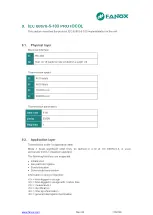
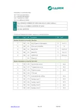
8.1.
ModBus package format
CUSTOMER
ADDRESS
1 byte
Each device on a communication bus must have a unique address,
otherwise two different units could reply simultaneously to the same
request. All ports of the relay will use this address which can be set a value
between 1 and 247. When the master transmits a frame with the slave
address to 0 indicates a Broadcast. All the slaves in the communications
bus will carry out the requested action, but no one will reply to the master.
The Broadcast will only be accepted to write, as it makes no sense to make
a read request in the Broadcast, as no one will reply this request.
FUNCTION
CODE
1 byte
This is one of the function codes supported by the equipment. In this case,
the only function codes supported are 3 to read and 16 to write. When the
slave has to reply with an exception one of these frames, it is indicated by
putting 1 in the most important bit of the correspondent function. Thus, an
exception for the function 3, will be indicated with a 83 as a function code;
and an exception for the function code 16 or 0x10 in hexadecimal, will be
indicated with an 0x90.
DATA
N bytes
This part consists of a variable number of bytes, depending on the function
code. It may include: addresses, data lengths, settings, commands or
exception codes sent by the user.
CRC
2 bytes
Control code of two bytes. The ModBus/RTU includes a 16 bit CRC in each
frame, to detect errors. If the slave detects an erroneous frame, based on a
CRC that is not correct, it won’t take any action, nor will reply anything to the
master. The management of the CRC is LSB-MSB.
DEAD TIME
Necessary
time to
transmit 3,5
Bytes
A frame is terminated when nothing is received for a period of 3,5 bytes. It
means:
15 ms at 2400 bps
2 ms at 19200 bps
...etc.
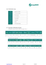
8.2.
Function codes
HEX
DEC
CODE
MODBUS NAME
DEFINITION
COMMENT
0x03
3
Read Holding
Registers
Reading of Any Value
This function allows the master to read
1 or more consecutive addresses of a
relay. The registers always are of 16
bits, with the most important byte at
first. The maximum number of
registers to be read in a package are
60.
0x10
16
Preset Multiple
Registers
Script
This function allows to write one or
more registers that represent one or
more settings. The registers are values
of 2 bytes of length, transmitted with
the most important byte at first. The
maximum number of register to be
written in a package is 60.
Содержание SIL-D00
Страница 8: ...www fanox com Rev 06 8 226 2 DIMENSIONS AND CONNECTION DIAGRAMS 2 1 Equipment front view...
Страница 9: ...www fanox com Rev 06 9 226 2 2 Equipment dimensions...
Страница 10: ...www fanox com Rev 06 10 226 2 3 Cut out pattern...
Страница 12: ...www fanox com Rev 06 12 226 Digital connections Only as an example...
Страница 13: ...www fanox com Rev 06 13 226 2 5 Terminals...
Страница 49: ...www fanox com Rev 06 49 226...
Страница 50: ...www fanox com Rev 06 50 226...
Страница 51: ...www fanox com Rev 06 51 226...
Страница 52: ...www fanox com Rev 06 52 226...
Страница 111: ...www fanox com Rev 06 111 226 I C 3 7 0 00 A C I N 4 7 0 00 A C V R 5 7 0 00 V D Ang 6 7 0 00 deg C IMax 7 7 0 00 A...
Страница 200: ...www fanox com Rev 06 200 226...
Страница 224: ...www fanox com Rev 06 224 226 14 9 Comments Person in charge of commissioning Date Maintenance performed on the by...
Страница 225: ...www fanox com Rev 06 225 226 NOTES...
Страница 226: ...www fanox com Rev 06 226 226...