


ETAS
ES430.1 - User’s Guide
92
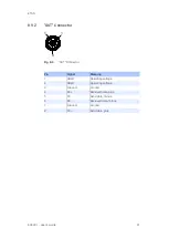
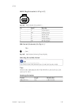
8.9.3
“Sensor” Connector
Fig. 8
-
4
“Sensor” Connector
Pin
Signal
Meaning
1
U
Batt+
Supply voltage, plus
2
U
Batt+
Supply voltage, plus
3
U
Heat+
Sensor heating, plus
4
U
Heat+
Sensor heating, plus
5
U
Heat-
Sensor heating, minus
6
U
Heat-
Sensor heating, minus
7
U
Batt-
Supply voltage, ground
8
U
Batt-
Supply voltage, ground
9
Analog-
Analog output, ground
10
RE+
Nernst voltage
11
IP
Pump current
12
RT
Trim resistance
13
IPN
Virtual ground
14
H_EXTEN
Enable sensor heating
15
U
Batt+
Supply voltage, plus
16
U
Heat+
Sensor heating, plus
17
U
Heat-
Sensor heating, minus
18
U
Batt-
Supply voltage, ground
19
Analog output, plus
20
TEDS-
TEDS-
21
TEDS+
TEDS+
22
n.b.
Not assigned
TIP
Analog ground (Analog-) and supply voltage ground (U
Batt-
) are galvanically
separated from one another.
Sensor heating plus (U
Heat+
) and supply voltage plus (U
Batt+
) are connected
internal.


