52
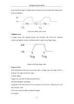
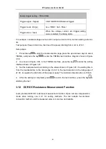
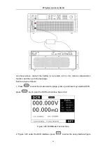
3.33.
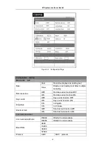
Figure 3.33 DCR Mode Setup Interface
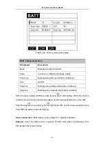
3. Set test parameters.
DCR Setting Parameters
Parameters
Note
Imin
Battery minimum discharge current
Imax
Maximum discharge current of battery
V Io
Lower limit for voltage comparison
V hi
Voltage comparison upper limit
R lo
Lower limit of resistance comparison
R hi
Resistance comparison upper limit
TrigMode
Automatic and manual
Delay2
Duration of load current per step
4. Press
to exit to the test interface and press
to start / stop the test.
3.13 Measurement item
The E-Load’s measurement items include: load-voltage, load-current, load-resistance,
load-power, ripple-voltage Vpp, and ripple-current Ipp.
3.13.1 Voltage, current, resistance and power measurement
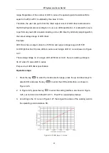
The E-load display the average voltage value and the average current value in real time at
measurement page. The maximum measurement bandwidth is 250kHz, and accurate
measurement can also be realized under large ripple conditions. The E-load provides two
measurement rates, fast and slow. In the harsh conditions, we recommend that you use slow
rate, which can achieve better stable reading. Voltage and current are set with two rangs (see
Chapter 4.1 System Settings for specific gear settings). Using small rang can achieve more
accuracy if necessary.
The value of load-resistance and load-power corresponding to load-voltage and load-current
can be read directly in the PARA column.
ET System electronic GmbH

