29
3. The E-load starts loading from 3A and stops at 6A in 100 steps with a step value
0.03A. The delay of each step is 0.01S. When the power supply voltage is less than the
1V trigger voltage, the corresponding current value is the OCP current value, and it is
judged whether the OCP current value is within the upper and lower limits of the current.
The test waveform is shown in Figure 3.9
3.4 EFFT Function
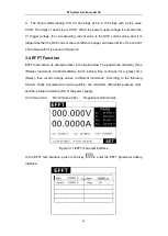
EFFT test function, its principle shown in the figure below. The load will be carried by three
different load-mode Imin\Inormal\Imax. Each loading time continues for a preset time
(Delay), then record voltage values in different load-mode. According to the following
formula, finally calculated the load-regulation, the maximum differential pressure (ΔV),
and the internal resistance (Rs) of the power supply.
ΔV=Vmax-Vmin; Rs=ΔV/(Imax-Imin) ; Regulation=ΔV/Vnormal;
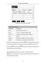
Figure 3.11 EFFT mode test interface
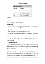
In the EFFT test interface, press to the key
to enter the EFFT parameter editing
interface.
ET System electronic GmbH


