30
EFFT setting parameter
Parameter
Description
Imin
Draw minimum working current
Imax
Draw maximum working current
Inor
Draw normal working current
Delay
Current duration per step
For example:
Source under test:
constant voltage source 24V, output current 0-5A, normal working
current 3A.
Purposes: to calculate regulation=ΔV/Vnormal
Operation steps:
1.
Press the key
to enter the mode selection page, press the up and down keys to
select EFFT, and press the key
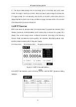
to enter the EFFT test interface, as shown in
Figure 3.11.
2.
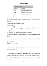
In Figure 3.11, press the key
to enter the setting interface
3. Set minimum current at 0A, maximum current at 5A, normal current at 3A, delay value
at 0.5S.
4. The E-load will carry the three setup currents separately, record the corresponding
voltage value, and calculate ΔV, Rs, Reg. Observe whether the Reg test value meets the
design requirements
3.5 Auto test function
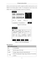
Auto test function is used for product inspection of the production line. The load current is
loaded and tested sequentially according to the steps edited in the file to automatic judge
the product qualified or not.
The E-load supports up to 8 files, each file supports up to 50 steps. Each load condition of
the step can be set, detection type (SPEC) and delay time (Delay). The delay time can be
set to wait for the trigger signal (when the time is greater than 99.99S), or it can be any
time ranging from 0.1S to 99.99S. The load condition supports a variety of working modes
ET System electronic GmbH


