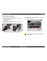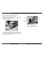
EPSON Stylus COLOR 880
Revision A
Disassembly and Assembly
Disassembly Procedures
97
12) Remove the several cables from the hook on the DE Assembly and
disconnect the connector from the PE sensor.
13) Slide the DE Assembly to the right.
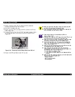
14) Remove two screws (No.3) securing the ASF/Pump Motor to the DE unit.
Refer to Figure 4-25.
15) Push down Planetary Gear 15.2 unit to the Pump drive engagement side to
release the pinion gear of ASF/Pump motor in the DE Assembly. (See
Figure 4-26.)
Figure 4-25. Removing the ASF/Pump Motor from DE Unit
16) Remove the ASF/Pump Motor from the DE Assembly.
ASF/Pump Motor
No. 3 Screws
DE Assembly
C A U T I O N
When you push down the hook in Step 9 to remove the DE
Lock Lever, be careful not to break the hook.
Do not damage the CR Encoder Slit plate when removing the
No.3 screw from the Top Frame in Step 11.
C H E C K
P O I N T
Check that all gears are assembled in the DE unit.
Refer to Figure 4-26.
Before you assemble the ASF/Pump motor to the DE unit, set
the Planetary gear 15.2 unit to the Pump drive side.
Make sure that the Panel FFC is placed on the bottom frame
before you assemble the DE unit to the Middle Frame.
Set the Tension Belt to the 17.19 gear of the Combination
Gear 17.19, 25.6 before securing the DE unit to the Middle
Frame. Refer to Figure 4-27.
Make sure that the three protrusions on the DE unit fit in the
corresponding holes in the Middle Frame.
After setting the Tension Belt to the Gear 22.92 of the
Combination Gear 12, 22.92, hang the Tension Spring 7.3 in
the following order. Refer to Figure 4-28.
1. To the hook on the Middle Frame.
2. To the hook on the Metal plate for the Combination Gear
12,22.92
Make sure that the following cables are set in the hook on the
DE unit when assembling the unit.
- PE Sensor cable
- ASF/Pump motor cable
- CR motor cable.
Содержание Stylus Color 880
Страница 9: ...C H A P T E R 1 PRODUCTDESCRIPTION ...
Страница 30: ...C H A P T E R 2 OPERATINGPRINCIPLES ...
Страница 55: ...C H A P T E R 3 TROUBLESHOOTING ...
Страница 76: ...C H A P T E R 4 DISASSEMBLYANDASSEMBLY ...
Страница 116: ...C H A P T E R 5 ADJUSTMENT ...
Страница 142: ...C H A P T E R 6 MAINTENANCE ...
Страница 152: ...7 APPENDIX C H A P T E R ...
Страница 164: ...EPSON Stylus COLOR 880 Revision A Appendix Circuit Board Component Layout 164 Figure 7 5 C298PNL Component Layout ...
Страница 177: ......
Страница 178: ......
Страница 179: ......


