EPSON Stylus COLOR 880
Revision A
Disassembly and Assembly
Disassembly Procedures
87
4.2.4.1 Removing the Printhead Unit
1) Remove the Upper Housing. (Refer to Section 4.2.1.)
2) Slide the CR Lock Lever to the front side with tweezers or small driver and
release the CR Lock Lever from the CR unit. Then move the CR Assembly
to the left.
3) Take both black and color ink cartridges out of the CR Assembly.
4) Remove the gray covers for black and color ink cartridges from the CR
Assembly.
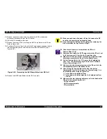
5) Remove the Head FFC Holder from the CR Assembly by releasing two
hooks. Refer to Figure 4-7.
6) Remove the two Head FFCs that connect to the Printhead Drive Circuit
Board built in the CR Assembly and remove the narrow FFC from the CR
Encoder Sensor Board on the CR Assembly.
7) Remove screw No.3 and slide the Print Head Unit to the left. Release the
hook on the right size and remove the Print Head Unit.
8) Disconnect the Ink Cartridge Detector Sensor Cable from the Print Head
Unit.
Figure 4-7. Removing the Printhead
No3. Screw
Head FFC Holder
Two hooks for
Head FFC Holder
C H E C K
P O I N T
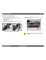
Make sure that the earth board is installed at the left of the
CR unit correctly. There are 2 pins used to determine the
location. Refer to Figure 4-8.
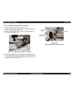
When you install the printhead to the carriage, make sure
that the two protrusions on the carriage side is placed in the
U-ditches of the printhead. Refer to Figure 4-8.
C A U T I O N
Since the ink cartridge once taken out can not be used
again, be sure to install a new ink cartridge when you
return the printer to the user.
Before packing the printer for transportation, make sure
new ink cartridges are installed and the carriage is locked
with the CR lock lever securely.
A D J U S T M E N T
R E Q U I R E D
When you replace the printhead unit, perform the following
adjustments. (Refer to Chapter 5 for more details.):
1.
Initial ink charge (Refer to Chapter 5/Section 5.2.3.9.)
2.
Head Voltage ID Input (Refer to Chapter 5/Section 5.2.3.5.)
3.
Bi-D Adjustment (Chapter 5 /Section 5.2.3.7.)
Содержание Stylus Color 880
Страница 9: ...C H A P T E R 1 PRODUCTDESCRIPTION ...
Страница 30: ...C H A P T E R 2 OPERATINGPRINCIPLES ...
Страница 55: ...C H A P T E R 3 TROUBLESHOOTING ...
Страница 76: ...C H A P T E R 4 DISASSEMBLYANDASSEMBLY ...
Страница 116: ...C H A P T E R 5 ADJUSTMENT ...
Страница 142: ...C H A P T E R 6 MAINTENANCE ...
Страница 152: ...7 APPENDIX C H A P T E R ...
Страница 164: ...EPSON Stylus COLOR 880 Revision A Appendix Circuit Board Component Layout 164 Figure 7 5 C298PNL Component Layout ...
Страница 177: ......
Страница 178: ......
Страница 179: ......


