Setup & Operation 3.3 Cable Connection (Installation)
26
RC420 Rev.9
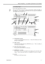
(1) M/C Power cable
This cable has round connectors with 17 pins on both ends. Connect the female
connector to the POWER connector at the Manipulator and the male connector to the
M/C POWER connector at the Controller. Insert the connectors and rotate
clockwise until you hear a “click”.
(2) M/C Signal cable
This cable has rectangular connectors with 68 pins on both ends. Connect the signal
cable to the SIGNAL connector of the Manipulator and the M/C SIGNAL connector
of the Controller.
(3) STANDARD I/O connector
This connector is for the user’s input/output devices. For details about STANDARD
I/O, refer to the
Setup & Operation 6. STANDARD I/O Connector
.
(4) EMERGENCY connector
The EMERGENCY connector has inputs to connect the Emergency Stop switch and
the Safety Door switch. For safety reasons, connect proper switches for these input
devices. For details, refer to the
Setup & Operation 5. EMERGENCY Connector
.
(5) AC Power cable
Cables for AC 200V (or the local equivalent) power supply to the Controller.
(6) Protective Earth Terminal connector
The Protective Earth terminal connects to the earth ground wire. The Protective
Earth terminal is better to be connected when a peripheral control unit such as a
sequencer is used in the system. Use a cable of size equal to or greater than AWG
#16 for the Protective Earth terminal.
(7) OPTIONAL DEVICE connector
Connect to optional operation units (e.g. ATTEND (TEACH) control device) or the
OPTIONAL DEVICE Dummy Plug. If neither is connected, the Manipulator will
be in the Emergency Stop condition and will not operate. For details, refer to the
Setup & Operation 4. OPTIONAL DEVICE Connector
.
(8) Mouse cable (Separate connectors)
Cable for a mouse.
(9) Keyboard cable (Separate connectors)
Cable for a keyboard.
(10) Mouse / Keyboard cable (Integrated connector)
This branch cable is for a mouse and a keyboard. Connect the cable to a mouse and
a keyboard following the symbols on the cable.
CAUTION
■
Connect the mouse and the keyboard properly when the power in OFF. If the
mouse or keyboard is connected when the power in ON or connected
incorrectly, the robot system cannot function properly.
Содержание RC420
Страница 1: ...Rev 9 EM073C1492F ROBOT CONTROLLER RC420 ...
Страница 2: ...ROBOT CONTROLLER RC420 Rev 9 ...
Страница 11: ...Setup Operation This manual contains information for setup and operation of the RC420 Robot Controller ...
Страница 12: ...Setup Operation ...
Страница 20: ...Setup Operation 1 Safety 10 RC420 Rev 9 ...
Страница 30: ...Setup Operation 2 3 Controller Part Names and Functions 20 RC420 Rev 9 ...
Страница 50: ...Setup Operation 5 5 Circuit Diagrams EMERGENCY Connector 40 RC420 Rev 9 ...
Страница 58: ...Setup Operation 6 3 Pin Assignments STANDARD I O Connector 48 RC420 Rev 9 ...
Страница 114: ...Setup Operation 10 UPS Uninterruptible Power Supply 104 RC420 Rev 9 ...
Страница 115: ...97 Maintenance This manual contains maintenance procedures for the RC420 Robot Controller ...
Страница 116: ...Maintenance RC420 Rev 9 106 ...
Страница 138: ...Maintenance 6 Motor Driver Module 128 RC420 Rev 9 ...
Страница 170: ...Maintenance 12 Recovering the HDD 160 RC420 Rev 9 ...


