


Setup & Operation 2. Specifications
38
G6 Rev.21
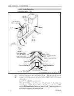
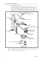
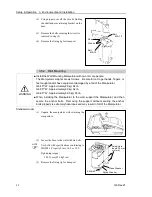
*1: The exhaust system in the Cleanroom-model Manipulator (G6-***C*) draws air from the base interior and
arm cover interior.
A crack or other opening in the base unit can cause loss of negative air pressure in the outer part of the
arm, which can cause increased dust emission.
Do not remove the maintenance cover on the front of the base.
Seal the exhaust port and the exhaust tube with vinyl tape so that the joint is airtight.
If the exhaust flow is not sufficient, dust particle emission may exceed the specified maximum level.
Cleanliness level : Class ISO 3 (ISO14644-1)
Amount of Dust (0.1 µm diameter or larger) in 28317 cm
3
(1cft) sample-air around the
center of the motion rang: 10 particles or less.)
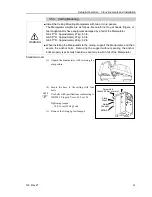
Exhaust System : Exhaust port diameter : Inner diameter: ø12 mm / Outer diameter: ø16 mm
Exhaust tube
: Polyurethane tube
Outer diameter: ø12 mm (Inner diameter:ø8 mm)
or Inner diameter ø16mm or larger
Recommended exhaust flow rate : Approx. 1000 cm
3
/s (Normal)
ESD specification uses resin materials with antistatic treatment. This model controls adhesion of dust
due to electrification.
*2: IP (International Protection) for the Protected-model Manipulator indicates International Standard of the
protection level against dust and water.
Normal G6-***D* Manipulators do not have bellows. The normal G6-***D* Manipulator (without
bellows option) operates under adverse conditions with oily mist.
If necessary, select the bellows option at shipment.
The Manipulators with bellows (option) comply with grade of protection IP54 (IEC 60529, JIS C0920).
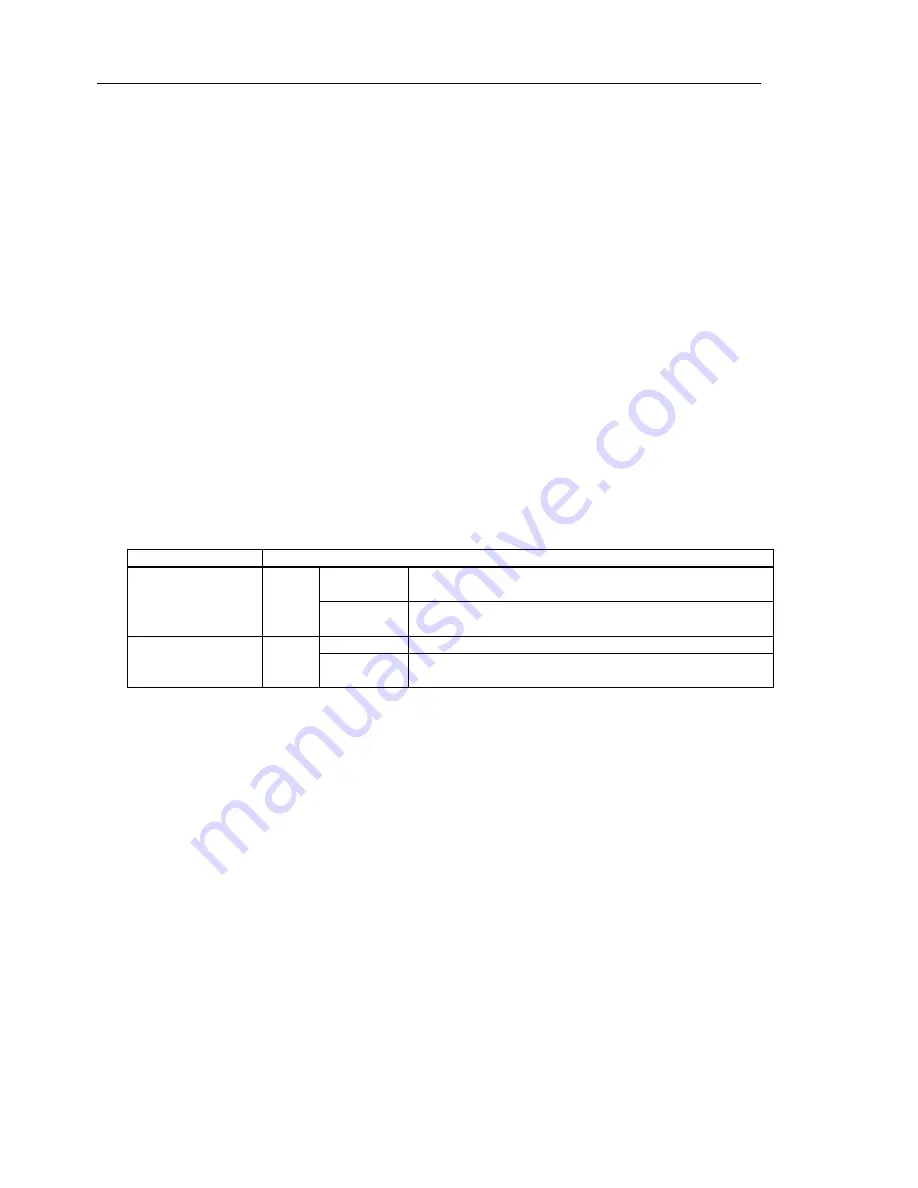
Model
Degree of protection
G6-***D*
with bellows option IP54
Dust : 5
Dust shall not ingress in a quantity to interfere with
satisfactory operation of the equipment.
Water : 4
Water splashing against the enclosure from any direction
shall have no harmful effect.
G6-***P*
IP65
Dust : 6
No ingress of dust.
Water : 5
Water projected by a nozzle against enclosure from any
direction shall have no harmful effects.
*3: In the case of PTP command. Maximum operating speed for CP command is 2000 mm/s on horizontal
plane.
*4: In the case where the center of gravity is at the center of Joint #4. If the center of gravity is not at the
center of Joint #4, set the parameter using Inertia command.
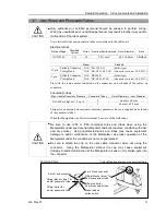
*5: Conditions of Manipulator during measurement as follows:
Operating conditions : Under rated load, 4-joints simultaneous motion, maximum speed,
maximum acceleration, and duty 50%.
Measurement point : Rear of the Manipulator, 1000 mm apart from the motion range,
50 mm above the base-installed surface.
*6: For delivery in April, 2008 or earlier, there are systems in combination of G series and RC170.
For delivery up until January 2017, there are systems in combination of G series and RC620.
*7: In general use, Accel setting 100 is the optimum setting that maintains the balance of acceleration and
vibration when positioning. Although values larger than 100 can be set to Accel, it is recommended to
minimize the use of large values to necessary motions since operating the manipulator continuously with
the large Accel setting may shorten the product life remarkably.
Содержание G6 series
Страница 1: ...Rev 21 EM183R3621F SCARA ROBOT G6 series MANIPULATOR MANUAL ...
Страница 2: ...MANIPULATOR MANUAL G6 series Rev 21 ...
Страница 8: ...vi G6 Rev 21 ...
Страница 14: ......
Страница 93: ...Maintenance This volume contains maintenance procedures with safety precautions for G6 series Manipulators ...
Страница 94: ......
Страница 120: ...Maintenance 4 Cable 108 G6 Rev 21 Table Top mounting Cable Unit Wall mounting Cable Unit Ceiling mounting Cable Unit ...
Страница 135: ...Maintenance 4 Cable G6 Rev 21 123 Table Top mounting M C Cable Wall mounting M C Cable Ceiling mounting M C Cable ...
Страница 216: ...Maintenance 14 Maintenance Parts List 204 G6 Rev 21 ...