


Maintenance 3. Covers
96
G6 Rev.21
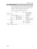
3.1 Arm Top Cover
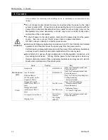
CAUTION
■
Do not remove the arm top cover forcibly. Removing the cover forcibly may
result in damage to the cables, disconnection, and/or contact failure. Damaged
cables, disconnection, or contact failure is extremely hazardous and may result in
electric shock and/or improper function of the robot system.
■
When installing the cover, be careful not to allow the cables to interfere with the
cover mounting and do not bend these cables forcibly to push them into the
cover. Unnecessary strain on cables may result in damage to the cables,
disconnection, and/or contact failure. Damaged cables, disconnection, or
contact failure is extremely hazardous and may result in electric shock and/or
improper function of the robot system.
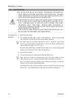
When routing the cables, observe the cable locations after removing the cover.
Be sure to place the cables back to their original locations.
Arm Top Cover
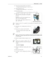
Removal
(1) Turn ON the Controller.
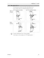
(2) Press and hold the brake release switch to let the shaft down. Be sure to keep enough
space and prevent the end effector hitting any peripheral equipment.
The brake release switch affects both Joints #3 and #4. When the brake release
switch is pressed, the brakes for both Joints #3 and #4 are released simultaneously.
(Joint #4 brake is installed to G6-**3** only.)
Be careful of the shaft falling or rotation while the brake release switch is being pushed
because it may be lowered by the weight of an end effector.
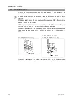
(3) Turn OFF the Controller.
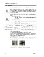
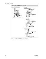
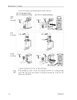
(4) Unscrew the arm top cover mounting bolts, and then lift the cover.
When bellows are installed to the manipulator, remove the upper bellows and then
remove the arm top cover. For bellows removal, refer to
Maintenance 9. Bellows
.
The cover cannot be removed completely because user wires and tubes are connected.
However, you can continue regular maintenance.
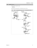
LED lamp and the cable of the brake release switch are located between the main part
and the cover. Do not pull the cable strong or the connector may be damaged.
NOTE
NOTE
Содержание G6 series
Страница 1: ...Rev 21 EM183R3621F SCARA ROBOT G6 series MANIPULATOR MANUAL ...
Страница 2: ...MANIPULATOR MANUAL G6 series Rev 21 ...
Страница 8: ...vi G6 Rev 21 ...
Страница 14: ......
Страница 93: ...Maintenance This volume contains maintenance procedures with safety precautions for G6 series Manipulators ...
Страница 94: ......
Страница 120: ...Maintenance 4 Cable 108 G6 Rev 21 Table Top mounting Cable Unit Wall mounting Cable Unit Ceiling mounting Cable Unit ...
Страница 135: ...Maintenance 4 Cable G6 Rev 21 123 Table Top mounting M C Cable Wall mounting M C Cable Ceiling mounting M C Cable ...
Страница 216: ...Maintenance 14 Maintenance Parts List 204 G6 Rev 21 ...