


Setup & Operation 2. Specifications
G6 Rev.21
25
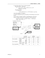
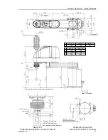
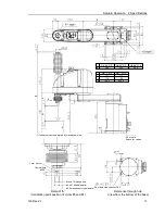
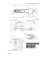
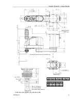
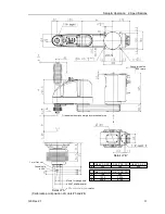
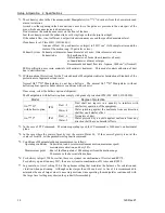
G6-45*SW
G6-55*SW
G6-65*SW
a
200
300
400
G6-**1SW
G6-**3SW
b
180
330
c
-9
141
d
385
535
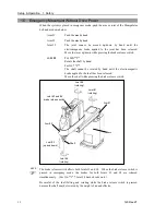
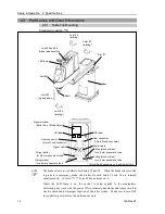
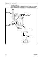
Space for cables
90 or more
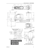
Reference through hole
(View from the bottom of the base)
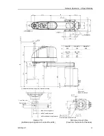
Conical hole
ø4,90°
1 mm flat cut
Max.ø14 through hole
ø20 h7 shaft diameter
ø40 mechanical stop diameter
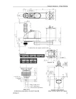
Detail of “A”
(Calibration point position of Joints #3 and #4)
(*) indicates the stroke margin by mechanical stop
Detail of “B”
Содержание G6 series
Страница 1: ...Rev 21 EM183R3621F SCARA ROBOT G6 series MANIPULATOR MANUAL ...
Страница 2: ...MANIPULATOR MANUAL G6 series Rev 21 ...
Страница 8: ...vi G6 Rev 21 ...
Страница 14: ......
Страница 93: ...Maintenance This volume contains maintenance procedures with safety precautions for G6 series Manipulators ...
Страница 94: ......
Страница 120: ...Maintenance 4 Cable 108 G6 Rev 21 Table Top mounting Cable Unit Wall mounting Cable Unit Ceiling mounting Cable Unit ...
Страница 135: ...Maintenance 4 Cable G6 Rev 21 123 Table Top mounting M C Cable Wall mounting M C Cable Ceiling mounting M C Cable ...
Страница 216: ...Maintenance 14 Maintenance Parts List 204 G6 Rev 21 ...