


Maintenance 13. Calibration
194
G6 Rev.21
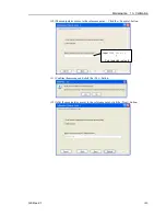
13.3 Accurate Calibration of Joint #2
When coordinates for the Manipulator working point require calculation, it is important
for Joint #2 to be calibrated accurately.
If the accuracy of Joint #2 is not obtained through the steps in the section
Maintenance:
13.2 Calibration Procedure
, follow the steps below “Calibration Using Right / Left Arm
Orientations” to accurately calibrate Joint #2.
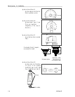
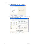
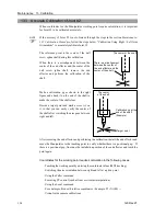
The reference point is the center of the ball
screw spline shaft during this calibration.
When there is a misalignment between the
center of the end effector and the center of the
ball screw spline shaft, remove the end
effector and perform the calibration of the
shaft.
The center of the shaft
There is a misalignment
between the center of
the end effector and the
center of the shaft.
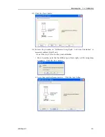
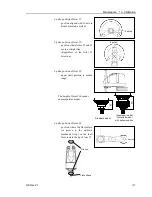
Make a calibration jig as shown in the right
figure and attach it on the end of the shaft to
make the center of the shaft clear.
Decide a target point and mark a cross (
×
) on
it so that you can easily verify the center of
the shaft after switching the arm pose between
right and left.
Calibration jig at the
end of the shaft
(Example)
Target point
The center
of the shaft
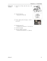
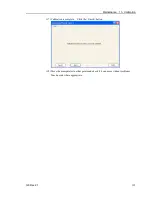
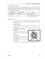
After removing the end effector and performing the calibration, install the end effector and
move the Manipulator to the teaching point to verify whether there is a positional gap. If
there is a positional gap, fine-tune the installation position of the end effector and teach the
point again.
Coordinates for the working point requires calculation in the following cases:
· Teaching the working point by entering the coordinate values (MDI teaching)
· Switching the arm orientation between right and left at a given point
· Using the Pallet command
· Executing CP control (such as liner or circular interpolation)
· Using the Local command
· Pose data specified with relative coordinates <Example: P1+X(100) >
· Vision Guide camera calibrations
NOTE
Содержание G6 series
Страница 1: ...Rev 21 EM183R3621F SCARA ROBOT G6 series MANIPULATOR MANUAL ...
Страница 2: ...MANIPULATOR MANUAL G6 series Rev 21 ...
Страница 8: ...vi G6 Rev 21 ...
Страница 14: ......
Страница 93: ...Maintenance This volume contains maintenance procedures with safety precautions for G6 series Manipulators ...
Страница 94: ......
Страница 120: ...Maintenance 4 Cable 108 G6 Rev 21 Table Top mounting Cable Unit Wall mounting Cable Unit Ceiling mounting Cable Unit ...
Страница 135: ...Maintenance 4 Cable G6 Rev 21 123 Table Top mounting M C Cable Wall mounting M C Cable Ceiling mounting M C Cable ...
Страница 216: ...Maintenance 14 Maintenance Parts List 204 G6 Rev 21 ...