


Maintenance 8. Arm #4
G6 Rev.21
155
U1 belt
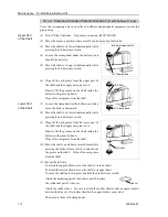
Removal
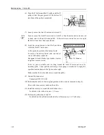
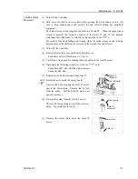
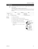
(1) Turn ON the Controller.
(2) Push down the shaft to its lower limit while pressing the brake release switch. Be
sure to keep enough space and prevent the end effector hitting any peripheral
equipment.
The brake release switch is applied to both Joints #3 and #4. When the brake release
switch is pressed, the respective brakes for Joints #3 and #4 are released
simultaneously. (The brake for Joint #4 is only installed to G6-**3**.)
Be careful of the shaft falling and rotating while the brake release switch is being
pressed because the shaft may be lowered by the weight of an end effector.
(3) Turn OFF the Controller.
(4) Remove the arm top cover and the arm bottom cover.
For details, refer to
Maintenance: 3. Covers
.
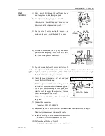
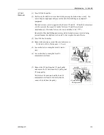
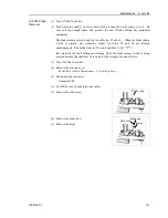
(5) Loosen the bolts securing the Joint #4 motor
unit.
4-M4
×
12
+
Washer
Joint #4
intermediate
shaft unit
Joint #4
motor unit
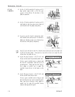
(6) Loosen the blots securing the Joint #4
intermediate shaft unit.
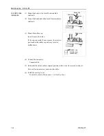
(7) Remove the U2 belt from the U2 small pulley
and remove the U1 belt from the U1 pulley and
U2 large pulley.
U1 pulley
Joint #4
Motor unit
Joint #4
Intermediate
shaft unit
U1 belt
U2 belt
U2 small pulley
U2 large pulley
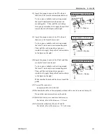
Put the Joint #4 motor unit and the Joint #4
intermediate shaft unit to the shaft side and
remove the belt from the pulley.
Содержание G6 series
Страница 1: ...Rev 21 EM183R3621F SCARA ROBOT G6 series MANIPULATOR MANUAL ...
Страница 2: ...MANIPULATOR MANUAL G6 series Rev 21 ...
Страница 8: ...vi G6 Rev 21 ...
Страница 14: ......
Страница 93: ...Maintenance This volume contains maintenance procedures with safety precautions for G6 series Manipulators ...
Страница 94: ......
Страница 120: ...Maintenance 4 Cable 108 G6 Rev 21 Table Top mounting Cable Unit Wall mounting Cable Unit Ceiling mounting Cable Unit ...
Страница 135: ...Maintenance 4 Cable G6 Rev 21 123 Table Top mounting M C Cable Wall mounting M C Cable Ceiling mounting M C Cable ...
Страница 216: ...Maintenance 14 Maintenance Parts List 204 G6 Rev 21 ...