30
EPSON
E0C6006 TECHNICAL MANUAL
CHAPTER 4: PERIPHERAL CIRCUITS AND OPERATION (Remote Controller)
4.9 Remote Controller (REM)
4.9.1 Configuration of remote controller
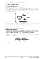
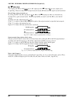
The E0C6006 has a remote controller (REM circuit) built-in. It can easily adapt to various remote control-
lers by connecting an infrared remote LED and a transistor as shown in Figure 4.9.1.1.
REM
(R33)
E0C6006
REM circuit
V
SS
V
DD
Fig. 4.9.1.1 Remote LED control circuit
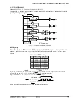
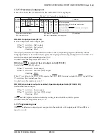
Figure 4.9.1.2 shows the configuration of the REM circuit.
OSC3
oscillation
circuit
f
OSC3
RCDIV
REMC
RCDUTY
τ
(Reference cycle)
generation circuit
RT1, RT0
ROUT1, ROUT0
RIC3–RIC0
Interrupt
counter
Interrupt
control
circuit
MPX
Interrupt request
REMSO
REM
(R33)
Carrier
Carrier
Carrier
generation
circuit
REMOUT
time
generator
REMOUT
τ
waveform
Fig. 4.9.1.2 Configuration of REM circuit
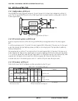
The generally used infrared remote controllers employ a method that generates transmission waveforms
in pulse modulation as shown in Figure 4.9.1.3 and transmits the signal.
First the transmission code is modulated in a pulse phase modulation (PPM) method to generate the
modulation signal, and the carrier that has constant frequency is amplitude-modulated (AM) using the
modulation signal. As a result, transmission waveforms are generated. Transmission is done by driving
the infrared LED using the transmission waveform.
Transmission code
0101
0
1
0
1
PPM
AM
Carrier
REM output
Fig. 4.9.1.3 Remote transmission method
In this remote controller, the carrier generated from the carrier generation circuit is controlled to turn the
output ON and OFF and the transmission waveform is generated. This transmission waveform can be
output from the REM (R33) terminal. At initial reset and while remote output stops, the REM terminal
goes low level (V
SS
).
The carrier frequency and duty ratio can be selected by the software from among 4 types. (details are
explained later)

