E0C6006 TECHNICAL MANUAL
EPSON
19
CHAPTER 4: PERIPHERAL CIRCUITS AND OPERATION (Output Ports)
4.5.3 Special output
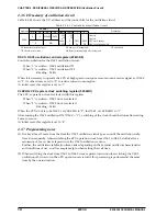
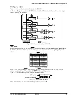
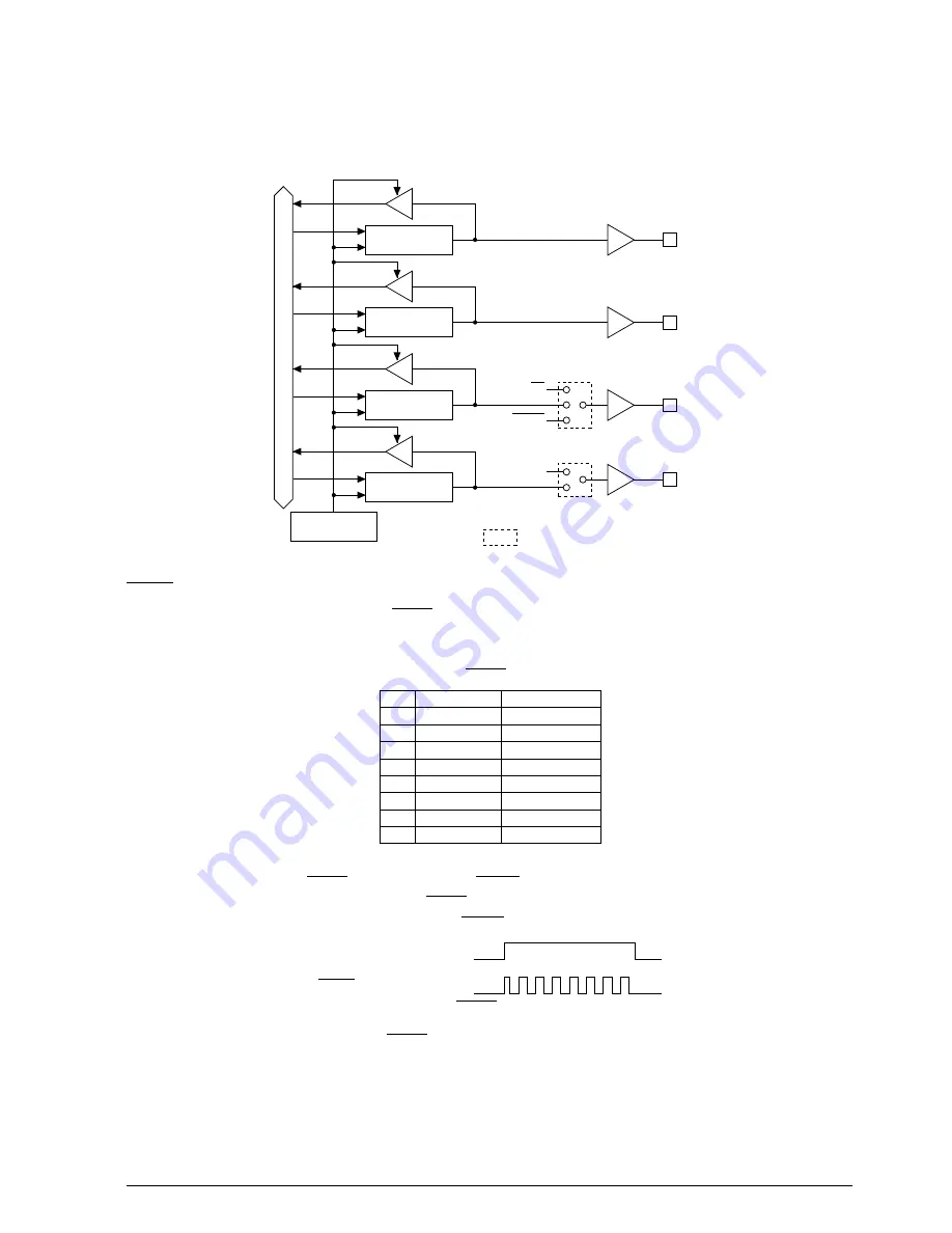
Figure 4.5.3.1 shows the structure of output ports R00–R03.
As shown in the previous section, the R02 terminal and the R03 terminal can be used as special output
ports by selecting mask option.
Register R00
Data bus
R00
Register R01
R01
Register R02
R03
R02
BZ
BZ
FOUT
Register R03
Address 0FCH
Mask option
Fig. 4.5.3.1 Structure of output port R00–R03
FOUT (R02)
When the output port R02 is set as the FOUT output port, the R02 will output the clock generated from
the OSC1 oscillation clock (f
OSC1
). The clock frequency can be selected from among 8 types by mask
option
Table 4.5.3.1 FOUT clock frequency
Dividing ratio
f
OSC1
f
OSC1
/2
f
OSC1
/4
f
OSC1
/8
f
OSC1
/16
f
OSC1
/32
f
OSC1
/64
f
OSC1
/128
Frequency
*
32768 Hz
16384 Hz
8192 Hz
4096 Hz
2048 Hz
1024 Hz
512 Hz
256 Hz
No.
1
2
3
4
5
6
7
8
∗
When f
OSC1
= 32.768 kHz
When "1" is written to the FOUT (R02) register, the FOUT (R02) terminal outputs the clock with the
selected frequency. When "0" is written, the FOUT (R02) terminal goes low.
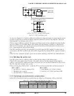
Figure 4.5.3.2 shows the output waveform of the FOUT output.
R02 register
FOUT output waveform
0
1
0
Fig. 4.5.3.2 FOUT output waveform
Note: A hazard may occur when the FOUT signal is turned on or off.


