E0C6006 TECHNICAL MANUAL
EPSON
7
CHAPTER 2: POWER SUPPLY AND INITIAL RESET
2.2.3 Oscillation detection circuit
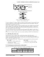
With RESET = H, the oscillation detection circuit receives f
OSC1
and makes a f-V conversion. If the OSC1
frequency is greater than a certain value, the oscillation output goes to L to clear the reset state. The time
required for f-V conversion depends on f
OSC1
, and is several milliseconds with f
OSC1
= 32 kHz. This time
gives a delay for clearing the reset state from the RESET input going to H.
The oscillation detection circuit may sometimes not operate normally with the initial resetting due to the
circuit, depending on the method of making the power, you should utilize the initial resetting method by
the RESET pin.
2.2.4 Watchdog timer
The watchdog timer guards the CPU against an unexpected overrun. It uses the OSC1 clock as the source
oscillation frequency to perform the increment operation. If the watchdog timer fails to be reset in 3–4
seconds with f
OSC1
= 32 kHz, the CPU will be initialized at initial reset.
See Section 4.2, "Watchdog Timer", for details.
2.2.5 Initialization by initial reset
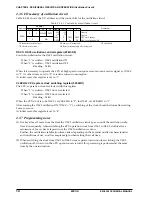
When the E0C6006 is initially reset, its internal registers are set as follows:
Table 2.2.5.1 Initial status
∗
See Section 4.1, "Memory Map".
Name
Program counter step
Program counter page
New page pointer
Stack pointer
Index register X
Index register Y
Register pointer
General-purpose register A
General-purpose register B
Interrupt flag
Decimal flag
Zero flag
Carry flag
CPU Core
Symbol
PCS
PCP
NPP
SP
X
Y
RP
A
B
I
D
Z
C
Bit size
8
4
4
8
8
8
4
4
4
1
1
1
1
Initial value
00H
1H
1H
Undefined
Undefined
Undefined
Undefined
Undefined
Undefined
0
0
Undefined
Undefined
Name
RAM
Display memory
Other peripheral circuits
Peripheral Circuits
Bit size
128
×
4
20
×
4
–
Initial value
Undefined
Undefined
∗
2.3 Test Input Pin (TEST)
This pin is used when IC is inspected for shipment.
During normal operation connect it to V
DD
.


