E0C6006 TECHNICAL MANUAL
EPSON
17
CHAPTER 4: PERIPHERAL CIRCUITS AND OPERATION (Input Ports)
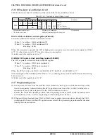
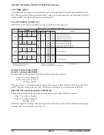
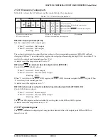
IK0, IK1: Interrupt factor flags (0F0H•D0, D1)
These flags indicate the occurrence of an input interrupt.
When "1" is read: Interrupt has occurred
When "0" is read: Interrupt has not occurred
Writing: Invalid
IK0 and IK1 are the interrupt factor flags corresponding to the input ports K00–K03 and K10–K13,
respectively. They are set to "1" at the falling edge of the input signal. From the status of this flag, the
software can decide whether an input interrupt has occurred or not.
These flags are reset when the software has read them.
Reading of interrupt factor flag is available at EI, but be careful in the following cases.
If the interrupt mask register value corresponding to the interrupt factor flag to be read is set to "1", an
interrupt request will be generated by the interrupt factor flag set timing, or an interrupt request will not
be generated. Be very careful when interrupt factor flags are in the same address.
At initial reset, this flag is set to "0".
4.4.5 Programming notes
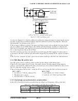
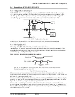
(1) When modifying the input port from low level to high level with pull-up resistor, a delay will occur at
the rise of the waveform due to time constant of the pull-up resistor and input gate capacities. Provide
appropriate waiting time in the program when reading an input port.
(2) Reading of the interrupt factor flag is available at EI, but be careful in the following cases.
If the interrupt mask register value corresponding to the interrupt factor flag to be read is set to "1", an
interrupt request will be generated by the interrupt factor flag set timing, or an interrupt request will
not be generated. Be very careful when interrupt factor flags are in the same address.


